diy solar

diy solar

BMS questions

c3auto

New Member
Joined
Jul 21, 2021
Messages
25
Hi all

I have some questions concerning BMS.

My system will comprise of 16x 320ah (allegedly) lifepo4 batteries from aliexpress into a 12v, 4S4P 1280ah system


As I have 16x cells I am thinking of dividing 4 cells into a bank with a BMS for each bank, with the 4 BMS' wired parallel to each other.

As this is a budget build I don't want to spend too much money on each BMS. I was thinking of utilising as cheap as possible BMS for each bank (thus one that doesn't have a display), and having one BMS with a display that I can use to monitor each bank of batteries via switches. I was thinking of using about a 50-80A BMS on each bank.

For monitoring purposes I want to utilise a 4S BMS with a display with each connection connected to a single pole 4 throw (or 5 throw?) switch.


As the 'display bms' is effectively in parallel with the existing BMS for each bank, can I select a lower amperage BMS for this purpose? I was also going to have a on/off switch to turn this display BMS on and off. The main purpose for this display BMS was to be able to monitor each cell voltage via the 4 switches for each bank, as well as perhaps selecting one bank, or, selecting the bad batteries of each bank to get an idea of the system performance as a whole. A 'representative' sample of 4 random batteries or a bank to represent the system as a whole.

My layout:

BMS 1 - Cells 1,2,3,4.
BMS 2 - Cells 5,6,7,8
BMS 3- Cells 9,10,11,12
BMS 4 - Cells 13,14,15,16.

DISPLAY BMS ( 4x single pole, 4 throw switch (or 5 throw switch to have a 0v reading so as to not have any current running through the switch?) ).

Switch 1 (Bank 1, with cells 1,2,3,4)
Switch 2 ( Bank 2, with cells 5,6,7,8)
Switch 3 (Bank 3, with cells 9,10,11,12)
Switch 4 (Bank 4, with cells 13,14,15,16).

OR
would it be more effective to do it this way, as the #1, 2, 3, 4 in each bank

So:
Switch 1 with cells 1, 5, 9, 13
Switch 2 with cells 2, 6, 10, 14
Switch 3 with cells 3, 7, 11, 15
Switch 4 with cells 4, 8, 12, 16.


1. Any suggestions for BMS current rating to get?
Assuming most power hungry scenario:
Running an aircon on max (2kw) for a few hours whilst concurrently induction cook top (2kw for 30 minutes twice a day).
4kw load ~ 333Amp single BMS, so the 4x BMS would be 80A? Can I go lower?

2. Suggestions for a cheap as possible BMS (for 50-80Amp)

3. Does my idea of using switches work? As its wired in parallel to existing BMS and its more of a display unit can I get a lower amperage BMS?

4. what current rating switches do I need to get? I'm assuming it won't have much current going through the display bms?

5. Any other alternative switch arrangement? or another way to monitor individual cell voltages.

6. I also have 4x 200ah winston cells i bought a number of years ago but didnt install yet. How would I best incorporate this into my system?


Thanks
 
For monitoring purposes I want to utilise a 4S BMS with a display with each connection connected to a single pole 4 throw (or 5 throw?) switch.
You do realize that each 4S BMS will have 5 balance leads and the main negative lead (B-) connections?
So switching your display between the 4 BMSs would be a LOT of wiring.

Why not get bluetooth BMSs and monitor them on your phone (or an old phone used only for the BMS app)?
 
KISS is the first rule of solar / battery systems.
If I understand you, you are going for a 12V system using 4 battery packs 12V/320AH for a total of 1280AH.
Place the assembled battery packs into a good parallel setup (same length & grade battery wires etc to good BusBars).
This switching thing is confusing. With 12V-4S BMS' you can get BlueTooth, RS232/485 Some with CanBus even, The simplest ones are the JBD 4S models with Bluetooth and the phone app. Some folks even have them working with Raspberry Pi's.

You will run into issues with 4000W / 333A extended draw, your Battery to Inverter wires will have to be 4/0, your BMS' will have to support high amperage in the 250A+ range. It would be far more practical to go to 24V Inverter system.

The Winston 200's have sat for a long time, if without charges over time and if now below 2.500V per cell, they likely suffered. They should be gently brought up in low amp <10A till 3.200 then you can increase the amps but don't go above 50A and terminate the charge at 3.600-3.650 with cells only taking 2A or less. Allow to settle for one hour and measure voltage & IR is possible. Check voltage hourly they should settle to 3.500 +/- a bit IF they are ok. Also, the difference between 320 & 200 packs is too much, the 120AH differential will adversely affect the entire bank as the 320's will have to support the 200 when it's low and te 200 will hit full before the others and that can be a problem too depending on the BMS's are configured an d if they are able to deal ith it.

The general unwritten rule is to not draw more than 250A from a battery bank (excepting surge handling). Stackable inverters and such are another matter handled differently.
12V@250A=3000W (25A AC),
24V@250A=6000W (50A AC),
48V@250A=12,000W (100A AC)
-- for quick reference. The (50A AC) can be 120V/50A out to panel or 240V/25A split phase to panel.
In simple terms. -- AC 120V/15A=1800W, 240V/15A=3600W uncorrected
? 250A. Because it's recommended to be the MAX draw limit for a standard"single" system. Single, meaning non-stacked inverters and similar.
! Inverter Wattage has to support the watts required plus surge capacity. Should never be run at the limit for an extended period of time (that's undersized).

Hope it helps, Good Luck
 
A cheap BMS is not going to be able to manage the other three BMS. Even the mid-priced BMS don't work that way. Each BMS is independent. Only when you get up into the high end BMS like Batrium (maybe REC) will you have that ability.

As suggested by MisterSandals, using bluetooth to monitor/manage the BMS is a good way to go. That's how I do it with my two BMS (4s2p).
 
Thank you I will be using 230v for the AC inverter

I will get a BMS with bluetooth monitoring as the extra hours in labor would be much greater than the cost savings in buying a better BMS.

I think I will also go with 24v for the 320Ah system (so 24v, at 640ah) , and maybe get a separate 12v BMS for the 200Ah winston batteries after checking they are OK. I was planning on using a dometic pure sine wave 350w inverter I bought to use with sensitive electronics (laptop etc) as well as lighting.

Should I be looking at a 7s or 8s system with 3.2v cells? I may in the future use this system on a 24v truck (the 24v alternator produces 25.5v). But the truck wouldn't be driven all that much and it would be a very small proportion of potential charging versus solar). I was also thinking of using the 24v system potentially as a starter battery as well for the truck. I briefly looked at the current requirements - the starter is a 4kw model, so @24vdc the starter would only need 166Amps for a few seconds to crank the motor over.

It seems very doable with a very large AH Capacity. I had looked into smaller cells with a high C rating but it was not feasible. Maybe I could utilise the 200ah winston cells as a 12v starter as well. My sprinter van has a starter (quickly looking on google) of around 1.7kw which at 12v is 141Amps for a few seconds max to crank the engine.

To charge the 12v battery bank from 24v,
Am I able to do something like a DC-DC charger from 24v to 12v, or am i better off converting to 230v via the inverter and then charging from there (due to maybe current limitations with a DC - DC charger)

Thanks again
A very helpful community here
 
Rarely do you find pure LiFePO4 batteries used to start engines. Small engines, sometimes. Big engines, no. The BMS usually doesn't support the very large surge required from the starter.

24v battery is going to use eight cells, so you need an 8s BMS.
 
Maybe I could utilise the 200ah winston cells as a 12v starter as well. My sprinter van
The Sprinter engine battery compartment is VERY confined and the battery is cradled in a plastic holder. It would be VERY difficult to modify this for a battery that had different dimensions.

If you use a battery maintainer like a Trikl-start powered by your house batteries, your engine battery can last a very long time. Mine lasted for 9.5 years being continually maintained.
 
Thank you
I will have to relocate the battery for the 12v system.

so for the 4S 12v 200Ah winston system, I am looking at a 40A or 60A BMS. I am looking at a daly one. Are these ok?

For the 8s 24v I am looking at 2x 100A BMS, again a daly brand.

The undervoltage cut offs seem a bit low. Any other BMS suggestions?

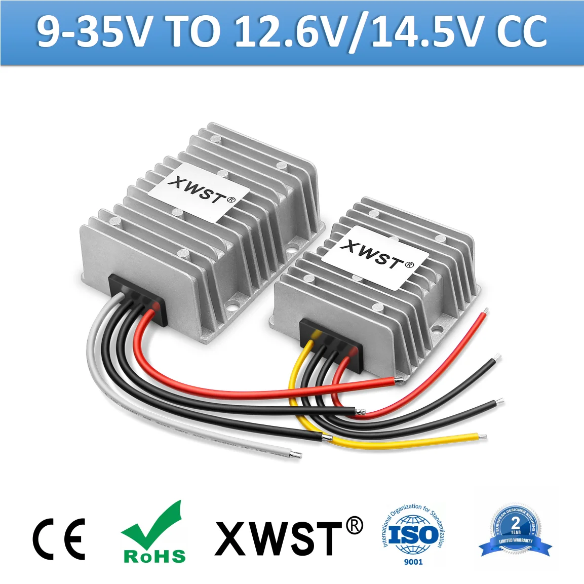
For charging I was going to get a constant current DC - DC Charger with an output voltage of 14.5V.

The 12v battery would be the starter battery so would also be alternator charged from driving as well.

Can I rely on the BMS of the 4S 12v to stop the charge and to start charging automatically with this constant current charger or should I opt for secondary protection as well through a voltage sensing relay?

any other secondary protection ideas?

Thanks again you guys are super helpful
 
Is there any reason you can’t go 16S to a 48 volt system? Induction power top and AC is a huge draw.

I would have loved to go 16S for 48 volts Instead of 8S2P for my build, but I would have to purchase new charge controllers, inverter, busbars, and master off switch, all to make be rate for voltages in excess of 48 VDC.

I can only say the Overkill BMSs I am buying would not be enough for your power requirements on a 24 volt system.
 
Well the charge controller i ordered is auto detection 12/24/48v
But the DC resetable fuses I bought are 12/24v, and the redundancy offered by 2 banks of 8s 24v is appealing to me if it comes to it.
48v equipment is also a bit expensive where I am from compared to 24v.

I will be running the inverters into 230v AC.

Is there any reason you can’t go 16S to a 48 volt system? Induction power top and AC is a huge draw.

I would have loved to go 16S for 48 volts Instead of 8S2P for my build, but I would have to purchase new charge controllers, inverter, busbars, and master off switch, all to make be rate for voltages in excess of 48 VDC.

I can only say the Overkill BMSs I am buying would not be enough for your power requirements on a 24 volt system.
 
I understand what you say about the price and availability.

I stopped looking when I found my SCCs were only 12/24. I never did see which busbars or switch I’d decide on. If it says rated to 48 volts, I take that to be the max voltage, not the battery voltage. Depending on the system, could see into mid-60 volts for an equalization.
 
The 12v battery would be the starter battery so would also be alternator charged from driving as well.

Can I rely on the BMS of the 4S 12v to stop the charge and to start charging automatically with this constant current charger or should I opt for secondary protection as well through a voltage sensing relay?
Using a LiFePO4 battery as a starting battery is not very common because of the number of amps required to turn over an engine. The BMS required would have to be very big and would make it cost prohibitive in my opinion. Having a lead acid starting battery maintained by a house battery trickle charger is a quite good solution.

Is there an issue you have with having a lead acid starting battery? What problem are you trying to solve?

I'd lean towards a larger house battery(s). If you want redundancy then maybe a pair of 8S batteries in parallel. You could have 2 different arrays and SCCs to charge this for redundancy too.
Personally, I like the idea of a 2P8S battery (i have and love a 2P4S battery in my Sprinter with a single Overkill BMS).
 
The van has been sitting a while so the battery will likely die soon. Instead of spending $100 on a new starter battery I thought i could utilise the 200ah lifepo4 bank i have sitting around.
I like the idea of having the 200ah lifepo4 bank as the starter. I can also run the headlights, keep the stereo on, and a few other things without having to worry about over discharging the traditional starter lead battery. I can also run other circuits from the 12v battery (like external LED flood lights) and utilise it as a more traditional deep cycle battery. I could also have a dashcam running 24/7 in the front and rear of the van wired directly to the battery.

I understand the starter peak currents are high.

Assuming a 1.7kw starter motor, as 12v it would use 142amps to crank the engine over. This would take a maximum of 5 seconds. Assuming 142 amps / 3600 seconds x 5s (max duration of crank) would be 0.2 amps used per starting cycle.
Is my calculation correct?

As my 12v power bank would be 200ah this would be okay for the discharge rating of the cells as it is (at 142 amps) less than 1C of the 200ah bank.

If say after 6 months the batteries seem fine I would also investigate having anderson plugs connected to the front and the rear of my van for easy access to jump start other vehicles more easily. Perhaps even just from the battery bank itself and not having to have my engine running.

The limiting factor as you guys have mentioned would be for the BMS.

I have had a look at cheaper daly 4s bms and the 60A would be able to do it with the 'sparkle' current?

1627112510990.png
 
OK, these are ESS Cells NOT LFP EV-Cells (in LFP there IS a difference) (which can do 5C Burst) and NOT intended for that sort of use as a "starter Battery". A Square hole, round peg. The boaters, RV'ers and MANY MORE have learned these lessons and some very costly lessons to boot. It's your money, so your lesson to learn, at what cost depends on you.
 
OK, these are ESS Cells NOT LFP EV-Cells (in LFP there IS a difference) (which can do 5C Burst) and NOT intended for that sort of use as a "starter Battery". A Square hole, round peg. The boaters, RV'ers and MANY MORE have learned these lessons and some very costly lessons to boot. It's your money, so your lesson to learn, at what cost depends on you.

But even with 142 amps (1.7kw, at 12v = 142A), that is less than 1C.
Am I missing something there? Are my calculations for cranking current correct assuming a 1.7kw starter for my van?

I did look at a lifepo4 starter a few years ago with something like 5C as you mentioned. But this is a big battery bank and the C rating is less than 1C based on a 200ah bank
 
The rule of thumb I found said your should have 1 CCA for every cubic inch of displacement and 2 for diesel. So 3 liters is 183 ci which equates to 366 CCA for a Sprinter.

 
Thanks my sprinter is an OM651 2.1L which is 128 cubic inch. Double that is 256amps. It never drops below freezing so hopefully it works with 200A.
Good news I measured the voltage of my lifepo4 Winston cells and they are all 3.33 ior 3.32. will do as mentioned in the above and see how they go
 
Hi all

I have some questions concerning BMS.

My system will comprise of 16x 320ah (allegedly) lifepo4 batteries from aliexpress into a 12v, 4S4P 1280ah system


As I have 16x cells I am thinking of dividing 4 cells into a bank with a BMS for each bank, with the 4 BMS' wired parallel to each other.

As this is a budget build I don't want to spend too much money on each BMS. I was thinking of utilising as cheap as possible BMS for each bank (thus one that doesn't have a display), and having one BMS with a display that I can use to monitor each bank of batteries via switches. I was thinking of using about a 50-80A BMS on each bank.

For monitoring purposes I want to utilise a 4S BMS with a display with each connection connected to a single pole 4 throw (or 5 throw?) switch.


As the 'display bms' is effectively in parallel with the existing BMS for each bank, can I select a lower amperage BMS for this purpose? I was also going to have a on/off switch to turn this display BMS on and off. The main purpose for this display BMS was to be able to monitor each cell voltage via the 4 switches for each bank, as well as perhaps selecting one bank, or, selecting the bad batteries of each bank to get an idea of the system performance as a whole. A 'representative' sample of 4 random batteries or a bank to represent the system as a whole.

My layout:

BMS 1 - Cells 1,2,3,4.
BMS 2 - Cells 5,6,7,8
BMS 3- Cells 9,10,11,12
BMS 4 - Cells 13,14,15,16.

DISPLAY BMS ( 4x single pole, 4 throw switch (or 5 throw switch to have a 0v reading so as to not have any current running through the switch?) ).

Switch 1 (Bank 1, with cells 1,2,3,4)
Switch 2 ( Bank 2, with cells 5,6,7,8)
Switch 3 (Bank 3, with cells 9,10,11,12)
Switch 4 (Bank 4, with cells 13,14,15,16).

OR
would it be more effective to do it this way, as the #1, 2, 3, 4 in each bank

So:
Switch 1 with cells 1, 5, 9, 13
Switch 2 with cells 2, 6, 10, 14
Switch 3 with cells 3, 7, 11, 15
Switch 4 with cells 4, 8, 12, 16.


1. Any suggestions for BMS current rating to get?
Assuming most power hungry scenario:
Running an aircon on max (2kw) for a few hours whilst concurrently induction cook top (2kw for 30 minutes twice a day).
4kw load ~ 333Amp single BMS, so the 4x BMS would be 80A? Can I go lower?

2. Suggestions for a cheap as possible BMS (for 50-80Amp)

3. Does my idea of using switches work? As its wired in parallel to existing BMS and its more of a display unit can I get a lower amperage BMS?

4. what current rating switches do I need to get? I'm assuming it won't have much current going through the display bms?

5. Any other alternative switch arrangement? or another way to monitor individual cell voltages.

6. I also have 4x 200ah winston cells i bought a number of years ago but didnt install yet. How would I best incorporate this into my system?


Thanks
a bms is a safety device...
those cell hold loads of power, dont cheap out on a bms please
 
Hi all, I charged up the winston sinopoly batteries in parallel to 3.60v and left them for a few days and they're at 3.40v now (still in parallel). I will attempt to charge them back to 3.60v a few times and see if they improve.

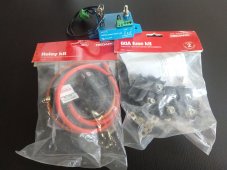
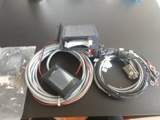
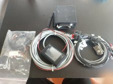
The batteries also came with a BMS! But no manual or anything as well as a few 60A fuses and stuff but I'm not sure if I can use it for my 12v battery system as i was looking into a bigger fuse. (Maybe I could use the battery protect for the 350w pure sine wave inverter). I'd use a separate fuse for the starter system.

I couldn't find a current rating for this BMS and no idea what it is. Can anyone tell me if it's any good?

I bought the whole package and batteries from a guy on eBay a number of years ago.
 

Attachments

  • IMG_20210801_142241363.jpg
    IMG_20210801_142241363.jpg
    222.4 KB · Views: 8
  • IMG_20210801_142101538.jpg
    IMG_20210801_142101538.jpg
    237.4 KB · Views: 7
  • IMG_20210801_142108981.jpg
    IMG_20210801_142108981.jpg
    211 KB · Views: 7
  • IMG_20210801_142044493.jpg
    IMG_20210801_142044493.jpg
    225.3 KB · Views: 8
they're at 3.40v now (still in parallel). I will attempt to charge them back to 3.60v a few times and see if they improve.
I am not sure what there is to improve upon. If they self discharge and settle equally, thats far more important that what exact voltage they settle to (within reason of course).

All my 40 cells of different size and shape settle to 3.35V (its crazy really). Some folks have theirs settle to 3.5V. I am thinking yours will settle where they want to. So seeing if they are similar would be my recommendation.
 
Back
Top