diy solar

diy solar

BMS reading one cell incorrectly

Genawin

New Member
Joined
Jul 18, 2023
Messages
11
Location
Bristol ,United Kingdom
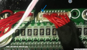
Hello this is my first time posting , I wondered if anyone has experienced similar ? Cell 9 of 16 x 300ah is reading up to 300mv higher on charge at 50a and 200mv lower on similar discharge than all the others which are closely balanced this indicated to me that I had a high resistance cell ,I have now replaced the cell and the problem remains so I investigated further to find that the BMS is falsely reading this cell. I also found that the correct cell voltage is getting back to the pcb so the problem appears to be the BMS itself , I have tried to identify which BMS I have and it appears to be a lot like a JBD or Heltec - the pcb is marked "VKL_01 ? , I'm able to use VKing V2.B to monitor, check history and do certain configurations but there doesn't appear to be any form of calibration to individual cell readings which doesn't surprise me , any help would be much appreciated.

IMG_20230915_094335.jpgScreenshot (184).png
 
It really does sound like you have confirmed the BMS is faulty, however you might want to just swap that cell and the bus bars on it to another location just to be sure.
 
Since the cell voltages are differential, I think it's possible that a neighboring pack could be bad. It seems unlikely, but, if it's easy, you might want to shuffle around the packs around the one that's reading bad to see if it changes anything.

Edit: Thinking about it a bit more, it's possible that the voltages are being read by two A2D banks with 8 inputs. That would put this battery at the bottom end of the second bank, so, if the reference voltage was varying for that A2D, it would likely show a result like this. That voltage would be created from the 8th battery. I don't know why that one would read correct but produce an incorrect reference voltage, but I think that's the one I would check first if I were considering the possibility of a neighboring battery being bad.
 
Last edited:
I also found that the correct cell voltage is getting back to the pcb so the problem appears to be the BMS itself
So, what you saw, presumably, is that the voltage of cell 9, when measured at the BMS, only differs by a small amount when a 50A charge or discharge is applied, but the BMS itself is incorrectly reporting a 500mV swing?
 
Thank you for your replies , I'm up against it when it comes to swapping cells as they have all been laser welded together and was tricky enough to just change the one cell , I'm getting accurate voltages (inc.8 and 10) back at the pcb that are reflected in correct BMS readouts all bar cell 9.
 
I would definitely lean on the battery pack manufacturer to send you a replacement BMS then. It's not one I recognize at all.
 
Yes I did when we thought it was the cell and they felt it was impossible to change the cell due to the laser welding so gave me a partial refund and then blocked me from all communication !:mad:
 
Cool Lithium , not sure if I'm allowed to put a link ?
Yes you can place a link & description of the battery in question.

Another check you can do before changing BMS'.
1) Check the connection of the sense leads on the cells to ensure they are tight & correct.
2) Check the connectors on the BMS, it is not unusual to have the wire connector push out of the plastic plug. There is only a small plastic tang that holds the metal sleeve in place. Just push the wires in from the back.

Also check the wire for Cell-9 if this is not resolved by a loose connection. Test it from end to end to ensure there is no break in it.

The BMS shown in Pic-1 is a bit different compared to JBD,JK,Daly.... this appears more like a Seplos or TNT, possibly a Pace but not likely.

See if that software app has a Help/About or FAQ or anything else that might give you a clue as to the origin of the software & BMS... If there are any links, do post them.

Hope it helps, Good Luck
 
Since the cell voltages are differential, I think it's possible that a neighboring pack could be bad. It seems unlikely, but, if it's easy, you might want to shuffle around the packs around the one that's reading bad to see if it changes anything.

Edit: Thinking about it a bit more, it's possible that the voltages are being read by two A2D banks with 8 inputs. That would put this battery at the bottom end of the second bank, so, if the reference voltage was varying for that A2D, it would likely show a result like this. That voltage would be created from the 8th battery. I don't know why that one would read correct but produce an incorrect reference voltage, but I think that's the one I would check first if I were considering the possibility of a neighboring battery being bad.
I like your way of thinking , you are right about the two banks but I've not noticed any variation, all other cells are very stable and well balanced including cell 8.
 
I don't know what your capabilities are (or desires are) for SMD repairs if you find what's broken, but I would try to identify the A2Ds and trace back the reference voltage line for the second bank to see if that voltages is changing when charging/discharging. Even if you just find the chip and are able to get a part number off it it, it might provide some clues.
 
I again agree with your way of thinking and Yes I have done a couple of SMD repairs but that was 12 years ago and I was on my limit of capabilities then - that was BMS faults on a couple of ev's !, I might consider it if I can find the fault and identify the component but I found that work very difficult. Thank you webbbn.
 
Not an expert on BMS design, but I thought they shared an ADC or two, rather than having one per cell :unsure:. So, if that is the case, a faulty ADC would show up with issues on other cells too? Maybe a fault in the switching logic circuit instead?

But, either way, if I were you, I'd see if I can beg, borrow or steal another BMS and attach that to the pack - far quicker and simpler than welding cells of getting your microscope out to do a SMD repair!

Pretty bad practice of the manufacturer to block you so quickly - not very professional for a company that claims "13 Years Professional Factory with 3 buildings" :(
 
Update - I've bought a replacement BMS - JBD UP16s010 200A as I was looking into the best way to tackle the change then noticed that there's no connection from cell 9 negative to the pcb so I'm tempted to try it but thought it best to see if anyone could explain why the original has facility for this but is not connected and yet the replacement JBD askes for this connection in the instructions, is this some kind of reference point to increase accuracy or to counter any potential voltage drop in the leads between the two 8 cell stacks ?
 

Attachments

  • Screenshot (193).png
    Screenshot (193).png
    548.7 KB · Views: 13
That's because the negative terminal of the 9th battery is connected to the positive terminal of the 8th battery. You should have 17 voltage sense wires going to a 16S pack (0S-16S). The positive end of the 8th cell and the negative end of the 9th cell are both the 8S voltage.
 
That's because the negative terminal of the 9th battery is connected to the positive terminal of the 8th battery. You should have 17 voltage sense wires going to a 16S pack (0S-16S). The positive end of the 8th cell and the negative end of the 9th cell are both the 8S voltage.
Yes that is my point there is no need for the 18th feed so why is the facility there on both but is only utilised on the JBD - it's the only cell on the PCB that is asked for a negative and positive feed ?
 
Back
Top