


NewRuins
New Member
So this BMS doesnt have instructions matching what they sent me.
Sent 4 tiny temp sensors and the only available port that it could be is this prewired harnass with 8 Red and Black cables.
I thought most of the time the temp sensors had R G Y and you chained them together.
Do people think I just wire each temp sensor to its own RB pair? Is there polarity on these?

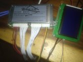
The last image shows the full package with the screen. The far right harnass has RGYB which matches with the communications port for the screen.
Sent 4 tiny temp sensors and the only available port that it could be is this prewired harnass with 8 Red and Black cables.
I thought most of the time the temp sensors had R G Y and you chained them together.
Do people think I just wire each temp sensor to its own RB pair? Is there polarity on these?
The last image shows the full package with the screen. The far right harnass has RGYB which matches with the communications port for the screen.
")