jyauxi
Farmer/Engineer/Economist
The following is a review/troubleshooting notes from my recently purchased JiaBaiDa UP Series 100a 16s parallel BMS (JBD-UP16S010-L16S-100A). I purchased these off the JiaBaiDa website directly and arranged for shipment.
I've had the BMS for roughly 3 weeks now and populating 5 boards with 16s 100a LiFePO4 batteries (CALB & Great Power). The hybrid inverter I am connecting them to is a pair of Deye 12kw 3-Phase Inverters (SUN-12K-SG04LP3-EU).
I will probably expand the system to several parallel packs but still to be determined if we will use this brand of BMS or not (or if there is something better).
Datasheet and Manual of the BMS can be located at this link.
The datasheet section is folded into the manual but is somewhat incomplete or not easy to understand. The IC used for instance are listed in #5 main material section instead of being upfront and listed out like most datasheet. The main microcontroller is HDSC HC32L072KATA (have not yet encountered this). The BMS IC is OZ3717 (again never heard of chip). If anyone has background on this, would be nice to connect.
JiaBaiDa does not have some quick start guide to use the BMS. But here are my notes:
The BMS requires a windows computer to configure/flash the firmware. The UP series uses a different program from other JiaBaiDa BMSes (probably because of parallel capability). The program can be found on their website.
Connection from the PC to the BMS is done via USB-UART or USB-RS485. The USB-UART adaptor they sell comes with the connector for the BMS (uses the LCD port). The USB-RS485 adaptor they sell DOES NOT come with the RJ45 plug so you have to crimp this yourself. The wiring method is indicated in the datasheet/manual.
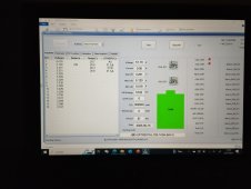
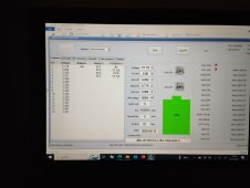
After starting the MJBD tools, select the com port of your USB-UART or USB-RS485 and the BMS defaults to 9600 baud. After confirming the com port and baud rate, there is a start button to initiate the connection. After which you should be able to see and configure the BMS.
When upgrading the firmware, I've tried using RS485 and failed, so it might be better to have a USB-UART adaptor to do this. When the firmware flashing has failed, it is possible to recover from this with the following steps:
I still have problems configuring the parameters since I want each pack to have 20a charge/discharge limit with 100a transient discharge. Still waiting on support for assistance on this,
I can confirm the CAN communication seems to be working since when I remove a battery pack, the Inverter decreases charge/discharge current. On the Deye Inverter, the inverter displays the battery pack as "LiBms:01".
I do want to have the BMS connected to solar assistant but the JBD RS485 protocol cannot recognize the BMS (probably because it has parallel communication and might have a different frame parameters. I am still waiting if JiaBaiDa will share the RS485 protocol.
My wishlist for this BMS is to also use the dry contacts to switch on/off an external active balancer based on individual cell voltage and switch off when voltage delta between the cells goes down or goes below a threshold voltage.
Generally an "OK" BMS for now. Still to be determined if it will meet my expectations to expand my battery packs with this brand.
Does anyone else have this BMS? What do you think?
I've had the BMS for roughly 3 weeks now and populating 5 boards with 16s 100a LiFePO4 batteries (CALB & Great Power). The hybrid inverter I am connecting them to is a pair of Deye 12kw 3-Phase Inverters (SUN-12K-SG04LP3-EU).
I will probably expand the system to several parallel packs but still to be determined if we will use this brand of BMS or not (or if there is something better).
Datasheet and Manual of the BMS can be located at this link.
The datasheet section is folded into the manual but is somewhat incomplete or not easy to understand. The IC used for instance are listed in #5 main material section instead of being upfront and listed out like most datasheet. The main microcontroller is HDSC HC32L072KATA (have not yet encountered this). The BMS IC is OZ3717 (again never heard of chip). If anyone has background on this, would be nice to connect.
JiaBaiDa does not have some quick start guide to use the BMS. But here are my notes:
- Wire up the battery sense leads. There are 4 connectors, each with a temp sensor. They've labeled the cables 1, 2, 3, 4 and cables 1 and 3 have leads connected to the negative pole of cell 1 and cell 9.
- Attach the P- leads from the BMS to load/inverter. (note positive is directly connected to your load/inverter with your choice of protection in between).
- Wire up 3 ribbon cable to another board with all the connections to RS485/CAN/Dry Contacts/Indicator Lights/Switches.
- Add a latching switch (not supplied) CJ11. This is the main power button to start the BMS. Without this the BMS won't boot up.
- Attach the battery sense cables 1-4 in order.
- Double check all connections
- Attach the B+ cable to the positive lead of the 16th cell.
- Power up the BMS by turning on the switch connected to CJ11
The BMS requires a windows computer to configure/flash the firmware. The UP series uses a different program from other JiaBaiDa BMSes (probably because of parallel capability). The program can be found on their website.
Connection from the PC to the BMS is done via USB-UART or USB-RS485. The USB-UART adaptor they sell comes with the connector for the BMS (uses the LCD port). The USB-RS485 adaptor they sell DOES NOT come with the RJ45 plug so you have to crimp this yourself. The wiring method is indicated in the datasheet/manual.
After starting the MJBD tools, select the com port of your USB-UART or USB-RS485 and the BMS defaults to 9600 baud. After confirming the com port and baud rate, there is a start button to initiate the connection. After which you should be able to see and configure the BMS.
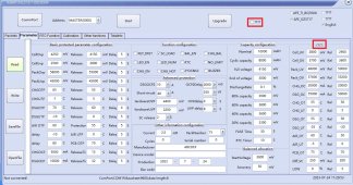
When upgrading the firmware, I've tried using RS485 and failed, so it might be better to have a USB-UART adaptor to do this. When the firmware flashing has failed, it is possible to recover from this with the following steps:
- connect the BMS using USB-UART (LCD port).
- power up the BMS (even if you get logboot failed, its ok)
- launch the MJBD tools
- select the com port and baud rate (IMPORTANT: Select 38400 baud rate)
- click on upgrade button (do not click on start)
- it may fail but you can try a couple of time before you get success.
I still have problems configuring the parameters since I want each pack to have 20a charge/discharge limit with 100a transient discharge. Still waiting on support for assistance on this,
I can confirm the CAN communication seems to be working since when I remove a battery pack, the Inverter decreases charge/discharge current. On the Deye Inverter, the inverter displays the battery pack as "LiBms:01".
I do want to have the BMS connected to solar assistant but the JBD RS485 protocol cannot recognize the BMS (probably because it has parallel communication and might have a different frame parameters. I am still waiting if JiaBaiDa will share the RS485 protocol.
My wishlist for this BMS is to also use the dry contacts to switch on/off an external active balancer based on individual cell voltage and switch off when voltage delta between the cells goes down or goes below a threshold voltage.
Generally an "OK" BMS for now. Still to be determined if it will meet my expectations to expand my battery packs with this brand.
Does anyone else have this BMS? What do you think?

")