diy solar

diy solar

Building the sickest ® VAWT ever. Brilliant minds unite please!!

@justgary ahh yes I was a bit ashamed to ask.

But now the CVCC seems stuck in CC mode. I cant find anything in the manual to break it out of that again other than the obvious.

Can you perhaps suggest something similar, yet contra, like you did earlier? to force the CVCC in a specific mode? or at the minimal out of CC mode.

The supply is always in CVCC mode.

You adjust the constant voltage first with the leads open, then adjust the constant current with the leads shorted. The supply will then not exceed either. When the load is small enough that it consumes less than the CC setting, the voltage limit will hold the voltage at the CV setting. If the load is higher than the CC setting, the voltage will be below the CV setting.

What are you seeing happen that suggests it is doing something different?
 
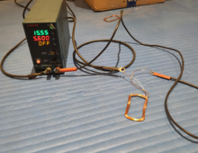
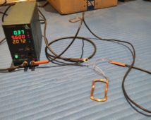
so I have a coil connected. This load is part of my testing procedure. It could be a part of the problem.

Being that when I turnoff turn on (as instructed in the manual) my settings are not adhered to

1708810813927.png

configured vs runtime
1708810863438.png
...
I am sure it is something simple I am overlooking. Or it is time to get out the big guns and get us a proper CVCC!
 
It looks like the first picture shows your settings, and the second shows what happens when you turn it on with the coil connected. The current is limited to 5.6 Amps, so it is at its limit. The voltage is based on the resistance in the coil.

Calculate the resistance as R = V/I, or 0.37V/5.6A, which is 0.066 Ohms. Verify the power shown with either P = V*I or P = I^2*R. That would be 5.6*5.6*0.066, which is 2.07 Watts, as shown on the supply.
 
I think that magnetic material between wires of a single coil hurts, does not help, create stronger field where you want it.
Lets see yes in practice. I have preliminary data that suggest otherwise.

I thin stacking coils is something to consider.

Given that we have no real way yet to make sure I am focusing now on the torque tests. It will allow us to see if stacking makes sense or not.


YEt!!!!!!!!!!!!!!
 
Ahh Yes @Hedges

Yes I also fell victim to this very natural intuition. WOW it got me sad for like 7 hours.

But then I realized this is not at play here. I still firmly believe that the coil fields will not interfere. The 3 phases are an actual team!!
 
Treating each other with respect like we are doing here seems to me the way to go forward. Now none of you here are addressed but I am just super upset as to why my fining out how to quantity a coil and magnet configuration was moved out of public viewing on fieldlines.

I get disappointed when the forces that be are working not with me.

I am losing my grip to be able to set a universally agreed upon standard on how to quantify the abilities of an alternator.
 
So I would like to create a band of brothers as to be able how to quantify things.

At firs we will need @OzSolar to lay out some ground rules.
And also to invite some people he knows to know their stuff.

The goal is how can we know if an alternator is capable of doing what it need to do.

Btw @OzSolar I have not forgotten about the challenge yes? You want to see at a minimum an annual worth of data not only in produce but also in maintenance of the structure?
 
Ok never mind then if not all superiors want to weigh in.

Then allow me to set the new standard on how to quantify things.

We use the gravity torque method.

Truth be told I am not really sure how it works and how we get to quantify things but at least I have got some measure and that is time.

So the context is having a weight of lets say 10KG attached to the disk.

With all coils open we measure how long it takes for the weight to hit the ground.

(I have around 2.3m height to play with here in my gym.)

Lets say it is 0.7 seconds as in a free fall. (it will never be that because of all the resistance of the whole setup)

and then we run the same experiment again with all coils shorted. Then we expect the weight to take longer to reach the ground.

Now the difference in time is what we are looking for. The more breaking force the shorted coils can produce the more power they can produce while charging a load.

I am not too worried about stalling as our turbine has a diameter and torque that is rather insane.

But the context is still indoor experiments.

can we say something about how to do this?
 
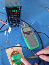
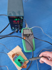
I realize these measurements are not taken very scientifically. But I am trying to establish if this iron powder can enhance the field of the electromagnets (coils)

1709031195257.png

1709031164810.png

Current casting is around 60% powder. I am not convinced yet of the benefit at this composition.

But given there must be some field enhancing properties I might as well just go ahead and push through.

And then use something like h-BN (boron nitrate) to fill up the rest of the casting to make sure that heat dissipation will have the most chance of success.
 
and to reitterate;

I am not taking things lightly.

Look at how intimidating a 2mm diam wire coil is at 30 winds.
1709032836227.png

now if only I can make them fit the 600mm inner radius template somehow.


Then things will become ... you know it already!!
 
Your first coil in the comparison above has a resistance of 0.181 Ohms. The second coil (with the iron powder filling) has a resistance of 0.195 Ohms. You didn't state the number of turns or wire gauge, so I can only guess that the first coil is maybe one or two turns shy of the second coil.

Also, you may have explained it already, but why do your coils all have elongated tails at the ends? It seems that you will lose some magnetic quality by spacing the turns out compared to keeping the whole coil tight.
 
ohh wow, I have gone and extended my search for a consensus and even on a dedicated science forum in my home country people have no real idea on how to proceed if consensus is what one is after!.

why do your coils all have elongated tails at the ends?

So they can be stacked. It is a tradeoff between the absolute shortest wire possible for a coil but then loose the ability to stack them.

Or go with this rather weird shape as for the ability to stack them to remain.
 
I meant to keep the ability to stack the coils as narrow as possible. Any shape can be stacked but then risk loosing the interaction between the oposing magnets on each rotor disk
 
Your first coil in the comparison above has a resistance of 0.181 Ohms. The second coil (with the iron powder filling) has a resistance of 0.195 Ohms. You didn't state the number of turns or wire gauge, so I can only guess that the first coil is maybe one or two turns shy of the second coil.
hmm good point. I tried winding identical coils.
Both 30 winds at 1mm diam each. The shape is to have each leg hover in between a magnet pair.

But I will admit that I stopped using the coil winder counter for these rather "small" coils. So indeed I might have just over wound or under wound.

But does not this put extra notice on the uselessness of around 60% powder?

I tried in the meantime 100% powder (no resin) and then the power running though it shot up to 21 watts. I had to cut that run short as temperatures were going well above the 70C limit.

0.195 Ohms / 30 turns = 0.0065 Ohm/turn
0.9965 Ohm/turn * 29 turns = 0.189 Ohms.
It looks like you probably did miss a turn.

Normalize the field generated by the number of turns, e.g. open coil:
4.53mT / 29 turns = 0.156mT per turn

Filled coil:
5.10mT / 30 turns = 0.17mT per turn

The filled coil produces 8.8% more field per turn than the unfilled one.
 
haha sorry for the confusion brother. I mean that I think and visualize in terms of a full rotation which I call a wind. Yet physics takes note of the length of the wire exposed to the field expressed sometimes as turns.


But it all boils down the the same thing eventually.
 
Back
Top