diy solar

diy solar

Building the sickest ® VAWT ever. Brilliant minds unite please!!

I meant the form you use to wind the coils. They should be tight and secure before you remove them from the winding form.
ahh ok. I use a standard pvc sewage pipe of 80mm diam to wind the coils. But I place small non abrasive wires in between the pipe and the coil before I begin as to make dislodging of the coil after winding so much easier.
 
Last edited:
If wound on a form first, then installed on stator:
1) Are they separate pieces to be spliced, or do they have a bit of length then go into next winding?
2) If varnished or otherwise bonded together, couldn't slip through gaps or press down into place. Shouldn't coils be loose prior to final installation?

The overlapping windings is easy in a straight line, but around a circle (is that radial or axial?), last one wants to be slipped under first one, at least for aesthetic reasons. Maybe first one lifts up to allow?
I have an actual coil template in the actual form of the coil. But that is only needed for the 1mm coil wire diam.

The 0.4mm wire can still be manhandled even after 300 winds. with the 1mm wire that is impossible at around 25 winds if my memory serves me well ;)

1) In this current test setup I keep each coil separate so I can play around with different configurations. Like testing a single coil and then in series or in parallel. Star or Delta and what has one.
But eventually once we have settled on a configuration then the coils, although modular, will become a fixed piece. I am aiming for 1/32 of modules.

2) I see where you are going. Yes I do not want the coils too tight while instaling them. Otherwise the powder cant get anywhere.
Think of it as massaging the coils in a bit. So that got me really nervous when Gary startled me.

Now I am planning on a print that can occupy the slots that have only 1 leg. So that there is even less chance for cogging because the print will occupy roughly the same amount of space as a coil leg would have.. But just to see how much of an issue that might be I am deliberately not doing that this early in the test. phase.
 
I meant the form you use to wind the coils. They should be tight and secure before you remove them from the winding form.
Sorry for my misunderstanding. I want the coils non tight and non secure. Otherwise the powder does not get enough chance to be banged in between the wires.

Can you please elaborate a bit why tight might be more optimal?
 
I found a dental lab oscillator/vibrator for under 80 euros. it will arrive tomorrow so then I will continue with the stacked 3 phase coil test.

In the meantime I am working on the air wheels
 
Sorry for my misunderstanding. I want the coils non tight and non secure. Otherwise the powder does not get enough chance to be banged in between the wires.

Can you please elaborate a bit why tight might be more optimal?
I would think that you want your cores inside the coils, but not physically touching them. Molding the cores and winding the coils separately would make life much simpler. Tight coils allow tight tolerances, thus reducing any air gap between the coil and the core. Tight coils also allow you to overlap the coil sets in a thinner fashion, which would increase your magnetic field.

Vibrating iron powder against copper wire is begging for a bunch of shorts.

You can make a simple bell jar to vacuum the epoxy after you pour. This will remove air bubbles and get higher density.
A bell jar might be needed indeed.

But massaging coils into a bath with a iron powder resin mix did not damage the enamel enough to make them lead to shorts.

I checked all the coils again and the readings are still very similar to earlier readings.

This tells me.

All systems GO!

Now we will see how it turns out after post curing. which will take a rather long time.

I have repurposed my old printer. (the one that I destroyed early on in this thread) to serve as the heat source of a DIY heat chamber.
1706194569598.png

Working like this I think I can get the powder contents much higher than before.

Now this dental lab vibrator is going back to amazon. What a load of crap that was. For this scenario one can better take off the sanding paper of a sanding machine and just go about it like that.
 
Ok so this heat chamber can not work unless the chamber is much smaller and also the piece to be heated directly on the bed.

Aim for as little space as possible between the chamber and the bed and the subject.

Even consider a chamber around the piece on the bed underneath the chamber around the whole setup.

Then it WILL work as I have already seen that in action. This is just me going to the other end of the spectrum and finding out that does not work.
 
To all current participators. Even though you might feel addressed. YOU are NOT

So I am thinking of a way to put a stop to the endless stream of snake oil to be found out there.

We have all seen it before.
A video on some kind of platform claiming a lot and showing impressive footage.

Somehow they all forget to do real word testing and include power potential. (how much breaking force the alternator actually has)

I am not really sure I will as go to making a graph at this time as it is time consuming and doing that early in the prototyping stage will mean a lot of extra time.

Nah, I better wait until my gut feeling tells me that this is something the world needs to know about. And that is only done via demonstration (and documentation so that it can be peer reviewed)

What I am complaining about in essence here is that somehow it is ok for random people to swoop in and say what ever they want. How ever unfunded (within limits because I know there are some good moderators here).

I would still like to get back to the subtopic of why there is no use for 6 phase over 3. I for one am a strong believer now that there is at least the use to fight coging. And if one want it to be even smoother then maybe 7 phase might be of help.

I do not like it when people come in and share their thought, in a rather definitive manner, and then when hitting resistance just shy away.

This is not how science evolves gang.

I do love it though when people share their thoughts!!!!!!!!!!!
 
Last edited:
Vibrating iron powder against copper wire is begging for a bunch of shorts
You might well be correct :(

Even though massaging in the coils into the iron powder resin did not short out coil #1. After running like 20 minutes of AC load through it it shorted out.

Now I have 1 hope left. And that is to properly post cure the piece before I start playing with it. But I was tooo impatient.

1706286297045.png


Ch1 is coil4 in isolation
Ch2 is coil2 and 5 in series.
Ch3 is coil3 in isolation.

1706286550888.png

Btw next casting will be with 50% winds. (150). There is not enough room for the iron powder to dissipate heat effectively.
Now I am only able to have the heat stabilized at 70C when running 9 VAC at 2.6 amps through all 6 coils wired in parallel.

this coil casting also failed because the coil legs shifted position so things might be out of optimal phase.
And it is too thick.
So this can not serve as a baseline. Just a fun experiment.
 
ohh wow!!

depending on how one winds a coil one can get 300 winds easy to pull apart. So that iron powder can creap easily into every space in between the individual wires. Yet also be compacted really thinly like 8mm high only once compressed in isolation. So no resin and powder around it.

please see on the left 150 winds and on the right 300 winds. on the 300 coil I opened up the back and the front is somewhat compressed.

These are wound in a narrow fashion rather that a wide fashion like the coils I wound earlier.

1706297354301.png

This tells me 2 things;
* That I still should see if I can get the heat dissipation ability back (like I demonstrated earlier with a single non stacked powdered coil) even in a 20mm thin stacked configuration. I think I can do it.
* That there is a lot of unused copper in the leg bends.. But I am putting on hold any attempts of also harvesting there as I already see that this alternator in its current configuration is going to generate far too much volts if the goal is 52 at 3.3 m/s.

So I am at a crossroads and I could really use some advice / opinions.
Do I keep pushing this concept and end up with voltages in the 200s and use a Midnight Classic MPPT controller to deal with that?
Or do I scale down to a more economical size as to reach the 52 volts at 3.3m/s?
I am leaning towards scaling down to give this design a chance to contribute to the world by reducing the bill of materials considerably.
 
this makes me also realize I should try winding coils narrow and then aim for much less copper.
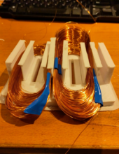
I have used this coil winding template shape for the narrow coils.

1706301151539.png

Now you see those 2 lines on the bottom and the top of the coil shape. That is how much I think I can cut of while winding coils since winding so narrow makes it so that I do not need the extra length of wire as to be able to stack/compress.

Lets see in practise if this works or not.
 
I think that magnetic material between wires of a single coil hurts, does not help, create stronger field where you want it.
As does extra long wire loops at the ends. Ideally the coil should be as compact as possible.
 
Gentlemen.

Let's stick to the context.

There are no more single coils if we keep as context a stacked array.

And yes I should be trimming down copper length to get a similar path length in the field.

Now although I think you are the only 2 brothers I have left participating in this journey on this site.

I still think it is important that we stick to the matters of hand. So at no point in time did make sense to me the most recent remark by Hedges.
 
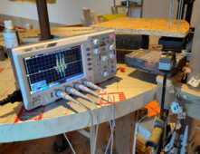
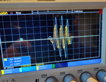
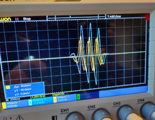
@justgary I have been struggling with the oscope manual but I am still not able to quickly destil a frequency from what I am seeing on the last imagec.

Now this unit does have all the bells and whistles to auto do that but I fear that will take me like 2 extra weeks of not continues time but practical spread time to get there.

If you would please give it another jab? I will make sure I will learn how to operate this oscope better.
 
Now to top it all off. I will also pull out the coil separator walls during the curing to also be able to reuse those and then there is absolutely no more space for any cogging to ever rear its ugly head. hmm that is my hypothesis at least. Lets see in practice how things go.
yeah NO!! do not pull out those separators for now. Unless one is really tuned in and experienced with casting epoy. It is better to just leave the walls there.

I am already sure these few mm of walls or not going to make a difference in terms of coggin. As I have found that is there NONE****.

****; Yeah sure there is always some but just so tiny that I could not notice it.

And the pla will probably stay in place all the time as the coils may not go over 70C while at full foce of operation. That is because the magnets will start misbehaving when at 80C.

Now I still am thinking of ways to ventilate the coils but I had rather find a setup that is rather thermally stable to begin with.
 
Last edited:
So at no point in time did make sense to me the most recent remark by Hedges.
You want the focus of magnetic energy to be at the center of the whole coil and perpendicular to the coil. Putting the core material around any particular wire in the coil will direct the energy in the wrong direction. Making the coil larger than it needs to be dilutes the energy.

Assume that the coil is the coil and the core is the core. They each have a job to do, and trying to make them share jobs only makes both less efficient. Make the coil as physically tight as you can all the way around, and make the core fit inside the coil, possibly with overhang at the top and bottom as @Hedges mentioned (the I or T shapes).
 
@justgary I have been struggling with the oscope manual but I am still not able to quickly destil a frequency from what I am seeing on the last imagec.

Now this unit does have all the bells and whistles to auto do that but I fear that will take me like 2 extra weeks of not continues time but practical spread time to get there.

If you would please give it another jab? I will make sure I will learn how to operate this oscope better.
Your scope probably has a frequency measurement function, but most likely it wants a continuous function to measure. In other words, it will not measure the frequency of a short blip on the screen.

In your recent photo, note how the blue trace conveniently crosses the center hash at the bottom of an oscillation. Note also that your scope is set to 200mS per division as shown at the lower left. Finally, note that the bottom of the third oscillation is about 2.6 divisions from the first crossing mentioned above:
2.6 divisions / 3 oscillations = 0.83 div./osc.
Now,
0.200 Sec / 0.83 div./osc. = 5.8 Sec./osc. (Hz).

It is always better to use as many clean oscillations as possible to create an average value that probably has better accuracy than measuring one oscillation.

Your scope probably has a "Cursor" function that will allow you to put horizontal or vertical (or both) lines on the screen where you want them, and it will measure the difference between the two. Your ability to place the lines is the deciding factor in the accuracy you get.

1706286550888-png.191440
 
@justgary I have been struggling with the oscope manual but I am still not able to quickly destil a frequency from what I am seeing on the last imagec.

Now this unit does have all the bells and whistles to auto do that but I fear that will take me like 2 extra weeks of not continues time but practical spread time to get there.

If you would please give it another jab? I will make sure I will learn how to operate this oscope better.

Frequency of this signal (as if the pattern repeated and wasn't just half a dozen times up and down)?

1706454065089.png

You could manually place cursors, get time between them, determine frequency from that.
Scope may have measure frequency function.
Scope may have FFT, which will show the frequencies (typically doesn't report the phase of each frequency) required to reproduce that waveform. Including the long flat sections. Assuming the pattern repeats itself again and again as if multiple screenshots lined up side by side.

But frequency just comes from your mechanical arrangement that moved the magnet over coils, unless it excited a resonance.
 
Now,
0.200 Sec / 0.83 div./osc. = 5.8 Sec./osc. (Hz).
Sorry, the coffee apparently hadn't kicked in. And never do math in public. Always write the full units down!

That's 1.0 / (0.200 sec/div * 0.83 div/osc) = 1.0 / 0.17 sec/osc = 6.0 osc/sec = 6.0 Hz.
 
Back
Top