diy solar

diy solar

Building the sickest ® VAWT ever. Brilliant minds unite please!!

anyway gang!!??

Did you really think I was really giving up?

Nah the true translation is that as long as I can no longer think of a new experiment I will back down on this.

------

hmm I thought of a new experiment. One that addresses the issue with the most recent findings.

You see that now it is no longer about me wanting to be special. NOW is is more about why does my findings not support my earlier findings.

screw this. I will gladly go into the books as the man that tried but failed to help science in this regard.

But I am not done yet. nah. not by a long shot I am not done yet.
 
so here I go again. expanding.

@justgary Am I allowed to either have as baseline some Hz more close to the the intended Hz.
Or am I challenged to go weird and then having to go though great lengths to eventually only showing that of course you were correct,as was hedges.

I can already reason why i had inconsistent results earlier. And I am now willing to admit that i do not wish to lay bare mother nature

So now we have a motor/.. A 3 KW strong one at that; how can this help us further?
 
All I am willing to content with still is that I have one final experiment to either confirm of disproof my train of thought.

You see that although I am really stupid in nature. I am sure relentless. and then when we work back it might be that I was never stupid to begin with.
And that the final results do not need to be in my favor for this process to be of benefit to science,. Any results will help the understanding for future generations.

I just want to understand why my logic based on my measurements is not consistent with my own further experiments.
 
I mean somewhere it has to be true.

I mean come on gang. It is easy to discern.

Just take your axial dual rotor setup and measure.

ohh wait. this is uncommon?

ok if that is true then I would like a addendum to all books ever written on the topic.
It seems there is much more information to be had which deserves a place in the books.
 
please bear witness to my first ever magnesium oxide powder cast.

View attachment 207255

I did not take any notes so I have no idea on the percentage.
Also these air bubbles seem to be only on the surface. the bottom of the casting seems to be totally without.

i do not know yet of a method on how to assess if there are bubbles in the middle of the casting.

Now I can consider getting a vacuum chamber but then only if it is established that this powder does indeed help to improve the thermal conductivity as opposed to just plain old resin.

{1}maybe just any old sanding machine without the paper on it and then let it vibrate on the curing casting. it might get the bubbles out. I should go and double check the abrasiveness of this element else risk ending up in the same pickle we were before Gary warned us of begging for shorts.{/1}

and as per usual I am open to suggestions of course
I just thought of just cutting this test piece like a pizza in slices.
I am thinking maybe 1/8 per slice.

that should give us an indication about whether or not the air bubbles only form on the top or throughout.
I do see that the bottom is smooth as a baby skin. So the trouble seems related to relative density of air vs this mixture in where bubbles want to move upwards.
 
so yes!!
a 35-70-35 coil but 3mm thick at a distance of 1mm from the lower rotor magnets. while both rotors are at their intended 17mm spacing.
Does wonders so it seems.

hold on to your buttocks!!
1712569949980.png
:)

So this leans towards a final configuration of 3mm coil in the bottom and top and 9mm of what ever (yet to be determined) in the middle.

Next up is to test if we have only powder in that 9mm in the middle will finally reconcile my understanding of how things should work or not.
 
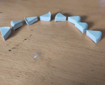
so this pizza is done.

I can only conclude that sure that there are weird layers there but the bubbles are only at the top surface.

Some of the pizza slices are on their back so all of the slices can demonstrate their least well cured part Nonsense. The bottom of the cast is always the best. I just tried to display the least best part of the cut..

1712575009646.png

I am not too worried when I look at that. especially given that I am only going to need about 3 mm of tickness and not this huge slab as it was a test run.
 
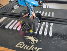
please forgive me, brother, for I have printed.

This is the preparation to a full 31 leg coil.

And since we are no longer concerned with high temp epoxy resin we can make due with poly resin just fine.
ETA is still 6:45 hours though :(

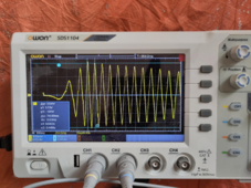
1712584165798.png
 
so yes!!
a 35-70-35 coil but 3mm thick at a distance of 1mm from the lower rotor magnets. while both rotors are at their intended 17mm spacing.
Does wonders so it seems.

hold on to your buttocks!!
View attachment 207865
:)

So this leans towards a final configuration of 3mm coil in the bottom and top and 9mm of what ever (yet to be determined) in the middle.

Next up is to test if we have only powder in that 9mm in the middle will finally reconcile my understanding of how things should work or not.
btw. would it help if I also translate what is determinable on the images I post?

I mean only recently I have learned how to read them by means of some good old fashioned rear ass kicking via the foot of one of our legends ;)

Nah but seriously? Would it help if I just tell in words what are the to discern?
 
try as I might, I just can't seem to confirm my logic.

The results are still on favor of non iron backed coils.

1712590019801.png

but in the grand scheme of things it really does not matter other than finally one has explored that avenue.

So all systems are still?

?

yes you have guessed it

GO
 
the gravity torque test is not working out :(

it is proving really difficult to get the PMA rotating at the intended speed with the coils closed.

So for a 29 leg coil of 5x 0.4mm litz wire I got only around 22 watts.

1712928684788.png
as I dropped a weight of 6 kg from 2.163 m height.
and open coil it took 4.95 sec
closed coil it took 45.32 seconds but the end speed was nearly not high enough as the intended speed.

I can add weights but there will always be a ramp up time needed and also then the disk would start spinning far too fast with the coils open.
Either I do not get how to properly conduct the gravity torque test or it is just not applicable in this scenario.

I do think though that this 5x 0.4 litz wired coil is not better than a single 1mm wired coil as the area is still less.
0.4 mm diam = 0.12566 mm2 * 5 = 0.6283 mm2
1 mm diam = 0.7854 mm2

what a complete waste having bought huge spools of 0.4 and 0.71mm wires.

if anyone can think of a good use for that?

I am now looking for a reliable way to measure the amps in the coils while shorted so that i can have the motor spin at the intended speed and then calculate the wattage the coils produce.
What would be the best tool to do that an accurate amp measurement?
 
Shunt or other current sensor, and scope or other logger.

Shunt resistor has to be sized for range and resolution.
DC current sensors like Hall Effect tend to have offset drift
AC current sensors will be good within some frequency range.

Perhaps a resistor selected for some current and voltage, rather than short circuit current, will be more interesting. With a short, it is like applying a brake so you can't easily get a decent speed and frequency.

Of course for PV panels we want to measure Vmp & Imp. For a coil, maybe Isc is useful but why not V(load) & I(load)?
 
ahh maybe wire car light bulbs in series / parallel until I get to the intended voltage and see when they explode?

for example 3 x 12 volt car lights in series for a 36 volt setup. and that in parallel a few times that it will be very hard to make them overheat / explode.

or I buy a proper resistor but how do I select it?
If I test with only 1 phase then the voltage should be around 37vAC

if I test 3 phases rectified I should have a resistor that is useful for a 52vDC scenario.
But I had rather not make all coils yet until I have some well taken data of a single coil. Because if it is really disappointing then I will have to get a new spool of wire. maybe 1.5mm in diam.

Or what I can also do is simply hookup the batteries directly but then not all 16 cells but 11 to match the 36 vAC atg the intended frequency.
but between reification with some capacitors in parallel to smooth out the output. although pulse charging should also be possible for what I have understood in the meantime.

Then keep ramping up the speed until either the battery cells or the coils reach some kind of temperature threshold which is 70C for the coils. All the while measuring the voltage and the amps at the same time

I mean that looks to me like a most realistic test I can think of but then I am worried I will destroy the cells while doing it.
 
Light bulb is non-linear resistor so either need to measure both voltage and current, or calibrate for its curve and operate long enough to reach steady-state.

Using battery as load, close to constant voltage so measure current. PWM or shunt regulator is common for turbines. I've always wondered if MPPT would work better. In the case of Pelton wheel, there is a particular speed (1/2 water velocity) which captures most energy; MPPT could find that or winding count can be designed for it. Wind turbine would be more complicated, variable wind speed and how airfoil behaves.
 
I like the idea of calibrating a car headlamp resistance curve with your bench supply. Turn the current limit all the way up and then record voltage and current as you incrementally increase the voltage. Then calculate resistance = voltage/current for each voltage. You now have a resistance curve for your particular lamp.

Now you can record your results from coil testing using that lamp as a load and calculate current = voltage/resistance (at that voltage).

I think a light bulb will hit its steady state resistance within a few milliseconds, but you could verify that as well with your scope by triggering on the voltage across the bulb and watching the curve as you make the connection.
 
it will be a challenge to get the motor to rotate slow enough and have the required torque to be able to rotate the PMA steadily. And then of course most certainly while the PMA is under load or shorted out even.

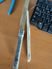
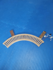
To that end I tried printing the least amount of teeth I could model to latch on to the motor.

I am so proud with the result. And that is even before I know if the T10 timing belt it self is happy to bend around such a small radius. I also do not even know if the little amount of PLA is strong enough to deal with the shear forces.

But who would have guessed that PLA, that is often looked down on, is in many ways one of the strongest filaments out there that is easy on us DIYers.

1712947302364.png

Only 5 teeth ;)

we will see.

I am going to start a nights long print now for the one on the PMA. with a size as large as my printer will allow for. To put on the PMA so that there will be a considerable speed reduction and also of course much less resistance for the motor to combat.
{1}that is not true at all. but I meant to say that then the available torque at the motor is far greater. or something like that I just do not know any better way to explain it. I guess you all know what it is I am trying to convey here{/1}

Yet if my printer decides to screw up again though mid print while I am sleeping I will have one of those dark rage against the machine ( not at all like one of my hissy fits ).

But then again it has been printing quite reliably recently after many many tweaks.
I do not even have to babysit the first layer (start process) these days :) For however long that might last :(
 
Last edited:
Back
Top