diy solar

diy solar

Buzzing DC breakers?

Sinewave inverters or inverter/chargers DC current has 2x the sinewave frequency in ripple current. For 60 Hz AC the peak to peak 120 Hz ripple current is about twice the average DC current.

At moderate battery current this 120 Hz ripple current creates strong 120 Hz magnetic fields around battery lines, including any DC breakers.

A good quality breaker should not buzz but a good breaker mounted in a metal enclosure with a loose cover lid may buzz the loose metal lid due to the 120 Hz pulsing magnetic fields.

If you bring the positive and negative cables close together, they will cancel out most of the magnetic field.

The pulsing on and off of the buzz in your recording is likely the float charging cycle coming on and off to maintain the float voltage on battery.
 
Last edited:
Sinewave inverters or inverter/chargers DC current has 2x the sinewave frequency in ripple current. For 60 Hz AC the peak to peak 120 Hz ripple current is about twice the average DC current.

At moderate battery current this 120 Hz ripple current creates strong 120 Hz magnetic fields around battery lines, including any DC breakers.

A good quality breaker should not buzz but a good breaker mounted in a metal enclosure with a loose cover lid may buzz the loose metal lid due to the 120 Hz pulsing magnetic fields.

If you bring the positive and negative cables close together, they will cancel out most of the magnetic field.

The pulsing on and off of the buzz in your recording is likely the float charging cycle coming on and off to maintain the float voltage on battery.
very informative... will have to re-read some time but my takeaway is that I need to look into quality DC breaker... any suggestions?
 
very informative... will have to re-read some time but my takeaway is that I need to look into quality DC breaker... any suggestions?
I would not worry about it unless the sound bothers you. If it is the breaker, it is likely the arc suppressor fins are made of some magnetic material that is vibrating in the plastic breaker housing.

On the graph, the green curve is what the inverter battery line current actually looks like.
Battery monitors and BMS's have an averaging low pass filter to remove the 120 Hz to get just the average DC current value.

Inverter waveform.png
 
Last edited:
I would not worry about it unless the sound bothers you. If it is the breaker, it is likely the arc suppressor fins are made of some magnetic material that is vibrating in the plastic breaker housing.

On the graph, the green curve is what the inverter battery line current actually looks like.
Battery monitors and BMS's have an averaging low pass filter to remove the 120 Hz to get just the average DC current value.

View attachment 89678
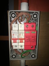
I see there's a lot of mentions about inverter stuff so I have to add that the DC breakers are connected to the solar panels

whenever the sun comes out and is giving my solar panels the business, those DC breakers will start buzzing
 
DC breakers are connected to the solar panels
Those DC breakers look top notch, i was kind of expecting something cheap or improper.
I wonder if there would be something interesting to be learned testing without the surge protectors?

Lets work onward. What does your array look like feeding these breakers?
 
How many amps are you pushing to those breakers?

I have noticed that the AC breaker for my EV charger will buzz if I set the charging rate to more than 80% of the breaker (I don't do it often, just for testing). My breaker is a quality Hager (German) breaker.
I know that for AC breakers, it's recommended not to push more than 80% of its rated capacity continuously.

Maybe the same goes for DC?
 
What charge controller?
That could be the source of pulsating current through PV or SCC breakers.
I wouldn't expect a magnetic DC breaker to buzz from steady current.
Another source could be inverter 60 Hz draw from battery and from capacitors in the SCC.

I had a cheap DIN transfer switch (2x 2-pole AC breakers interlocked.) Rated 63A, operating well below that.
Didn't trust it so I replaced with different kind.
 
How are your panels wired? Those look like 16 amp breakers. It's possible depending on how you have the panels wired that your going over the breakers limit. I noticed one breaker is darker colored then the other this could be an indication of over heating due to high amps.
 
Those DC breakers look top notch, i was kind of expecting something cheap or improper.
I wonder if there would be something interesting to be learned testing without the surge protectors?

Lets work onward. What does your array look like feeding these breakers?
four 350W (40.15V, 8.72A)
paired off in series
the buzz only starts whenever there's direct sunlight on the panels
 
If you hear buzzing on PV line breakers, when you expect to be pulling maximum available power, you are losing PV power. When regulating absorb or float battery voltage and less than available PV power is required, there may be PV breaker buzzing.

PV panels should not be subjected to any ripple current or you will be losing available PV power. Sun illumination creates a DC current source. To extract the most power from the panels it is important that the load is smooth and constant at the illumination based appropriate maximum power point loading with no ripple induced loading variance due to inverter/charger.
 
Is there an inverter powering any significant loads? Try shutting off inverter.

Inverter draws ripple current, and capacitors in SCC could be supplying some of that current. AC ripple current on top of DC current might go high enough the magnetic breaker mechanism starts to react.

If you have a clamp meter, read AC and DC current in SCC output wires. It should respond to 60 Hz, may or may not respond to switcher frequency.

PV panels should not be subjected to any ripple current or you will be losing available PV power. Sun illumination creates a DC current source. To extract the most power from the panels it is important that the load is smooth and constant at the illumination based appropriate maximum power point loading with no ripple induced loading variance due to inverter/charger.

I would expect PV panels to feed capacitor on input of SCC, fairly steady voltage (and therefore panel current) with slight triangle waveform. Buck converter switches so battery is charged through inductor from capacitor, then coasts through inductor and diode to negative. AC component of current in inductor (and through breakers) can be larger than AC component in PV, with capacitor filter making the difference.
 
I would expect PV panels to feed capacitor on input of SCC, fairly steady voltage (and therefore panel current) with slight triangle waveform. Buck converter switches so battery is charged through inductor from capacitor, then coasts through inductor and diode to negative. AC component of current in inductor (and through breakers) can be larger than AC component in PV, with capacitor filter making the difference.
It is rare to rely on capacitors on PV panel output for single phase AC load ripple elimination. Enphase did this on their original micro-inverters and quickly changed their approach on their next model.

It requires larger capacitors to do the ripple elimination sufficiently and slows down the MPPT adjustments making it sluggish and inefficient.

A grid tied inverter usually boost PV voltage to a high DC voltage that allows the HV filter capacitors to slump in voltage during the single-phase AC ripple load.

Many all-in one HF hybrid inverters do not have sufficient HV DC filter cap values to eliminate effects of ripple bleeding through to PV input.
Just look inside a Sunnyboy GT inverter at its quantity of HV filter caps and compare it to a similar wattage HF all-in-one hybrid inverter HV filter caps.

To be fair, the HF hybrid all-in-one relies on the battery to HV DC converter to fill in the AC output 60 Hz peak current so the HV DC does not slump too much but many cannot switch between charging battery and providing HV DC fast enough so the battery only protects PV from ripple pass through when battery is not charging. The PV ripple is most likely when PV input is near its high voltage limit end where it is close to the inverter's HV DC level. At lower voltage PV input it is not a problem.
 
Last edited:
Depends on what kind of SCC and inverter OP has.

I assumed separate SCC. If used with a low-frequency inverter, SCC output capacitors could be supplying some of its ripple current.
If HF inverter, I don't think much 60 Hz ripple on battery, but I haven't measured one.

If an AOI, depends on architecture. A few put PV MPPT output onto HV DC rail. I assume most put it on battery, and have HF inverter.

If this is GT PV inverter, then you're correct the PV decoupling caps have to buffer 60 Hz current. Unlike LF inverter which will mostly draw ripple from battery, GT PV would draw 100% from capacitor (to the extent it exceeds steady DC from PV.)

GT with boost as you describe would isolate PV from the ripple.
Some transformerless GT PV require PV voltage in excess of peak AC voltage. Those with transformers can do similar with a lower voltage.
But power/voltage curve of PV is fairly flat over a voltage range.

While voltage/current ramps up & down each cycle, the inverter can measure and track moving maximum power point. It's not a bug, its a feature!

I am just speculating that my Sunny Boys use capacitors on PV for the ripple. But I think it is likely, more efficient single conversion.

Enphase may have been driven by limited capacitance. Much more energy storage available with large voltage swing, and ceramics should tolerate that better than electrolytics. Just a different way to skin the cat.
 
When you have a direct to battery SSC you have lots of storage reserve for absorbing inverter 120 Hz ripple.

This is also the reason you should not use DC coupling for normal grid tied selling from a hybrid inverter. The batteries are the capacitors so the large ripple current will be impressed on batteries all the time the inverter is producing AC power output. This stresses the batteries even when there is no net average power draw from battery.

You need large AH battery if you are DC coupling PV into batteries and pulling large amount of inverter power. A large ripple current on a small AH battery will quickly damage battery. A common mistake is thinking you don't need much battery AH size because you have so much PV power available.

All direct to battery MPPT SSC DC to DC switchers use high frequency switching but the output filter cap is nowhere large enough to supply any significant 120 Hz ripple current.

All sinewave inverters, HF or LF, have 120 Hz (or 100 Hz for 50 Hz AC) ripple current on battery, at least above a few hundred watts of load. It would take Farads of capacitance on a 5-kW inverter input to reduce the single-phase sinewave power profile ripple current at battery voltage.

The use of HV DC on grid tied inverter and HF inverters is to leverage the amount of capacitance by allowing some ripple voltage slump on capacitors. But in the case of all-in-one hybrid inverters, when PV input is closer to inverter's HV DC there is not much capacitor voltage slump margin so the battery to HV DC converter has to be called upon to prop up the HV DC from slumping too much.
 
Last edited:
Back
Top