diy solar

diy solar

CAN and RS485 BMS Interface with multiple emulated Inverter protocols for JkBms Jbd BMS Daly 123Smart

I write the name of the bluetooth same as in the jk app which is "TSWS48V200-6" and it said BT Disconnected. Can you guide me?
What is the CAN Interfacee: UART CAN, BT CAN, RS485, DUAL means?
And also what is the difference between the BT protocol : JK02 JK02S, JK4?
also i don't have the SN65HVD230 to use can on my set up so i can only use rs485 i guess on my SPF5000ES so what is th protocol on the growatt should i set and with which pin and on the software what should i set?
Spf500es need CAN and porotocol 52 sonu need can tranciver sn6hvd230

Send a phkto with bms model
 
Spf500es need CAN and porotocol 52 sonu need can tranciver sn6hvd230

Send a phkto with bms model
So no need to use Max 485 then. here are the picture of the BMS JK-B1A24S15P

WhatsApp Image 2023-09-06 at 08.35.54 (1).jpeg
 

Attachments

  • WhatsApp Image 2023-09-06 at 08.35.54.jpeg
    WhatsApp Image 2023-09-06 at 08.35.54.jpeg
    655 KB · Views: 23
Key: f1c9093fb9d732b3211703dc5806e5de

Connect first the serial on bms put bt on off

Test the connection with the invertor pls, Other person with Deye 12k tell me some time appears w31 warning.
Can u confirm that issue?
I haven't had any W31 or F31 errors, so no problems on that front.
However, the module doesn't work with both a UART and BT connection for me. No issues with the UART, BT only doesn't show charging, discharging or SOC. Both together it sets the UART connected BMSs SOC to 360% and doesn't show charging, discharging or SOC for the BT connection either (even though they are there from the app once I disconnect from the ESP32) (It also only loads like half a page at most when viewing from a phone with both BMSs connected). I tried the latest 4.2B binary, still the same issues. Any guesses on how to fix it? Images attached.
 

Attachments

  • Screenshot_20230906-090900.png
    Screenshot_20230906-090900.png
    159.7 KB · Views: 13
  • Screenshot_20230906-091801.png
    Screenshot_20230906-091801.png
    162.5 KB · Views: 13
  • 2JKBMS.png
    2JKBMS.png
    197.9 KB · Views: 13
I haven't had any W31 or F31 errors, so no problems on that front.
However, the module doesn't work with both a UART and BT connection for me. No issues with the UART, BT only doesn't show charging, discharging or SOC. Both together it sets the UART connected BMSs SOC to 360% and doesn't show charging, discharging or SOC for the BT connection either (even though they are there from the app once I disconnect from the ESP32) (It also only loads like half a page at most when viewing from a phone with both BMSs connected). I tried the latest 4.2B binary, still the same issues. Any guesses on how to fix it? Images attached.
Try jk02s protocol for bt, if have 150a or 200a
Will check the soc issue
 
I haven't had any W31 or F31 errors, so no problems on that front.
However, the module doesn't work with both a UART and BT connection for me. No issues with the UART, BT only doesn't show charging, discharging or SOC. Both together it sets the UART connected BMSs SOC to 360% and doesn't show charging, discharging or SOC for the BT connection either (even though they are there from the app once I disconnect from the ESP32) (It also only loads like half a page at most when viewing from a phone with both BMSs connected). I tried the latest 4.2B binary, still the same issues. Any guesses on how to fix it? Images attached.
Can u send me some photo woth the carge voltage reded by invertor?
 
Try jk02s protocol for bt, if have 150a or 200a
Will check the soc issue
That fixes most of the issues with the BT connected BMS (except for temp, but that might be a BMS issue, since the external sensor report 0C, while it's actually 25C), however the SOC on the UART connected battery is still messed up.

Can u send me some photo woth the carge voltage reded by invertor?
Is this one sufficient or do you need the photo from the inverter itself?
 

Attachments

  • Screenshot 2023-09-06 110408.png
    Screenshot 2023-09-06 110408.png
    197.8 KB · Views: 6
That fixes most of the issues with the BT connected BMS (except for temp, but that might be a BMS issue, since the external sensor report 0C, while it's actually 25C), however the SOC on the UART connected battery is still messed up.


Is this one sufficient or do you need the photo from the inverter itself?
From the invertor display if u can check if the data are same on chaege voltage and charge curentt limit.

Other people try with Pylontech tell me disconecting and have some diffrent parameters.

Screenshot_20230906_123456_Samsung Internet.jpg
 
From the invertor display if u can check if the data are same on chaege voltage and charge curentt limit.

Other people try with Pylontech tell me disconecting and have some diffrent parameters.

Both Pylontech and Seplos seem to work intermittently, occasionally the inverter won't recognize the protocols.
Picture with Pylontech protcol and lithium mode 00 attached.
The current is half of what the inverter receives, so it's only reported from 1 BMS, the one connected with UART.

However, as soon as I connect the other battery with BT, SOC on UART connected battery goes to either 360% most of the time, or sometimes to 180%, which the inverter reports as 100%. Also, the ESP32 start to really lag with both connected, with just one it's quite quick.
 

Attachments

  • IMG_20230906_131735591_HDR.jpg
    IMG_20230906_131735591_HDR.jpg
    1.1 MB · Views: 16
Last edited:
Us3 bt protocol jk02s
Modify the namw with no space
Hello.The batterie is already communicate to the serial port and BT as well. but my problem is in my country we don't have the Can bus SN65HV230. Is there any way to bypass to connect to the SPF5000ES. I am desperate
 
Both Pylontech and Seplos seem to work intermittently, occasionally the inverter won't recognize the protocols.
Picture with Pylontech protcol and lithium mode 00 attached.
The current is half of what the inverter receives, so it's only reported from 1 BMS, the one connected with UART.

However, as soon as I connect the other battery with BT, SOC on UART connected battery goes to either 360% most of the time, or sometimes to 180%, which the inverter reports as 100%. Also, the ESP32 start to really lag with both connected, with just one it's quite quick.


Can u give me the invertor replay msg from page info, i will make a pach for u to test it on deye, to respond only after invertor replay and some difrent time replay
 
Hello.The batterie is already communicate to the serial port and BT as well. but my problem is in my country we don't have the Can bus SN65HV230. Is there any way to bypass to connect to the SPF5000ES. I am desperate
U can serch for other can tranciver module. Or buy one from ebay. Be shure is compatible with 3.3v
 
Can u give me the invertor replay msg from page info, i will make a pach for u to test it on deye, to respond only after invertor replay and some difrent time replay
What do you mean exactly? Are any of these pictures any help? Or do you need something else?
 

Attachments

  • IMG_20230906_193702159_HDR.jpg
    IMG_20230906_193702159_HDR.jpg
    1.3 MB · Views: 28
  • Screenshot_20230906-183608.png
    Screenshot_20230906-183608.png
    80.8 KB · Views: 27
What do you mean exactly? Are any of these pictures any help? Or do you need something else?

Om jk info page u have:
Inverter Disconected
Msg receive ID
Msg receive


Ur inverter is connected to can?
Normal the inverter send some Can MSG back evry 1s or more

That id and msg apeer there.

If no msg from inverter the inyerface will wait for it and from here can have lag.

If no msg for dmsome time interface will reset itself and can have the error protocol u say.

So to fix the protocol for ur inverter tell me if any msg received from invertor when plig it first time,

After I restart the ESP32, I get this:
InvertorConnected
CAN Receive Id0x305
CAN Receive Msg0-0-0-0-0-0-0-0
It stays connected up to an hour this way, based on Solar Assistant data (since the battery SOC will display as 100% when connected due to the UART BMS displaying 360%)., after that it will disconnect. After it disconnects, I don't know whether it shows the UART battery SOC or the one that Deye calculates, since those match very closely.

EDIT: Not sure if it matters, but even when the BMS is connected with the inverter, the BMS page on the inverter shows only half the current, so the BT connected battery data isn't included in there.
 
Last edited:
After I restart the ESP32, I get this:
InvertorConnected
CAN Receive Id0x305
CAN Receive Msg0-0-0-0-0-0-0-0
It stays connected up to an hour this way, based on Solar Assistant data (since the battery SOC will display as 100% when connected due to the UART BMS displaying 360%)., after that it will disconnect. After it disconnects, I don't know whether it shows the UART battery SOC or the one that Deye calculates, since those match very closely.

EDIT: Not sure if it matters, but even when the BMS is connected with the inverter, the BMS page on the inverter shows only half the current, so the BT connected battery data isn't included in there.

So u have problem with the SOC only when are 2 battery connected right? I Mean Serial + Bt in same time

I see u change on Li protocol, that work better then Pylon ?
 
Last edited:
So u have problem with the SOC only when are 2 battery connected right? I Mean Serial + Bt in same time
Exactly, only when both batteries are connectors. When it is UART only, everything is correct. The Ah number is also correct on both, it's just the SOC that's messed up on UART when both are connected.
 
Exactly, only when both batteries are connectors. When it is UART only, everything is correct. The Ah number is also correct on both, it's just the SOC that's messed up on UART when both are connected.

Ok, i will debug it this weekend, also i will activate Serial 1 to connect 2 jk on serial. u will need to use the pins from first photo.

Seems ur invertor send only one time the reg 0x305 , after some time if nothing is received the interface will write Invertor disconnected
This is only for info not make any change , the interface will continue to send CAN data even if aperar Invertor disconnect

Other invertors like Victron send also 0x305 but resend every 2s.

Thell me if Li protocol work better on deye then pylon ?

The difference is in LI no reg with name is send it , also the reg for errors and warnings is different.

When are 2 batteries
SOC is calculated (SOC1 +SOC2)/2
Nominal Capacity = n1+n2
Remain Capacity = r1+r2
Warnings / Alarms = w1 xor w2
 
Hi,

I will present my DIY CAN BMS emulator project , I work from some time to make this interface for integration of DIY battery with different brands of invertors with supported CAN or RS485 communication.

Interface use an esp32 with one or tow CAN ports and RS485 support, can handle multiple JK as inputs for data, and also cand handle LV or HV.

I use in this project all the data i can find online, i know am not the first on this road if u have documents of other BMS protocols u can share it with me.

If u want u can support my work to add more protocols to this project and buy the hardware components kit from my ebay or fallow on Patreon!

Hardware:

Esp32 DevKit 1
CAN : SN65HVD230
RS485: Max485
DC-DC: XL7015
RJ45 Breakout
Optional: Indicator LEDs

View attachment 156678

View attachment 156679
Connectivity:

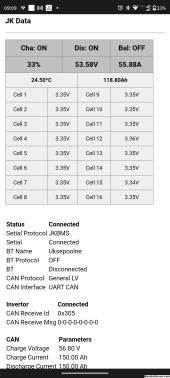
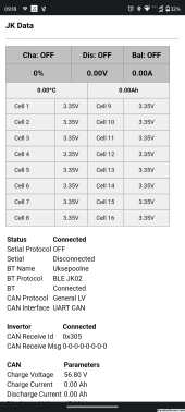
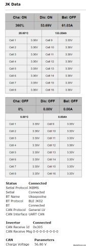
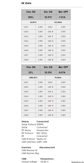
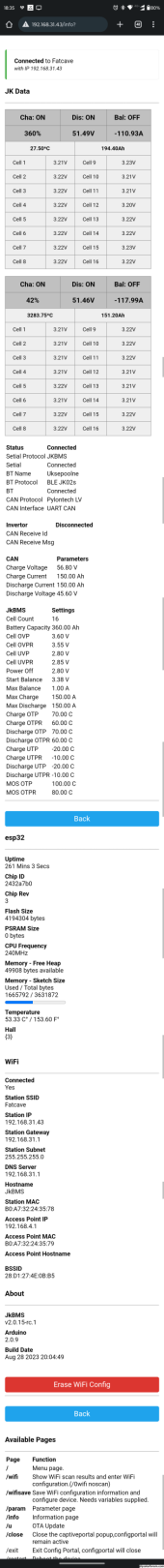
WIFI Web Portal with Cell Info Data on local IP

View attachment 156673
View attachment 156676


Input BMS supported:

View attachment 156674
JK BMS - TTL, BT , CAN
JBD BMS - BT connection
Daly - work in progress


Protocol Emulated:
View attachment 156675
General BMS LV
Document V1.4 - 07.09.2020
CAN: 500Kbps
Transmission Cycle: 1s
Data Mode: Little Endian

Pylonthech LV
Document V1.2 - 08.04.2018
CAN: 500Kbps
Transmission Cycle: 1s
Data Mode: Little Endian

Seplos LV
Document V1.0 - 08.04.2018
CAN: 500Kbps
Transmission Cycle: 1s
Data Mode: Little Endian

LG Resu LV
Document
CAN: 500Kbps
Transmission Cycle: 1s
Data Mode: Little Endian

Growatt LV
Document V1.04 22,02,2019
CAN: 500Kbps
Transmission Cycle: 1s
Data Mode: Big Endian

SMA LV
Document V1.0 - 07.09.2020
CAN: 500Kbps
Transmission Cycle: 1s
Data Mode: Little Endian

Li LV
Document V1.0 06.01.2020
CAN: 500Kbps
Transmission Cycle: 1s
Data Mode: Little Endian


Victron Nemea200
Document V1.0 06.01.2020
CAN: 250Kbps
Transmission Cycle: 1s
Data Mode: Little Endian


Pylon HV
Document V1.18 30.05.2019
CAN: 500Kbps
Transmission Cycle: 1s
Data Mode: Little Endian


GoodWee HV
Document V1.3 31.03.2021
CAN: 250Kbps
Transmission Cycle: 1s
Data Mode: Little Endian

BYD HV
Document
CAN: 500Kbps
Transmission Cycle: 1s
Data Mode: Little Endian

Pylontec RS485
Document V2.0 15.10.2019
RS485: 9600bps MODUBUS ASCII
Transmission Cycle: 0.5s Timeout
Data Mode: Little Endian

Seplos RS485
Document V3.3 21.08.2018
RS485: 9600bps MODUBUS ASCII
Transmission Cycle: 0.5s Timeout
Inverter Replay:
Data Mode: Little Endian

Growatt RS485
Document V2.02 24.07.2019
RS485: 9600bps MODUBUS ASCII
Transmission Cycle: 0.5s Timeout
Data Mode: Little Endian

BYD RS485
Document
RS485: 9600bps MODUBUS RTU
Transmission Cycle: 1s Timeout
Data Mode: Little Endian

Inverter Tested LV

Victron: Gx Family - General LV have the most information displayed, this is an combination of more registry i find.
Growatt SPF 5000 ES - Pylon LV, Seplos LV, Li LV
Growatt SPH 5000 TL - Pylon Lv, Seplos LV, Li LV, Growatt LV
Solis S5-EH1P6k - Semplos LV, LI LV
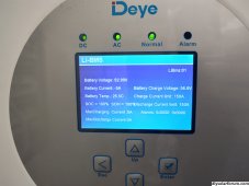
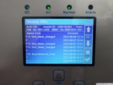
Deye SUN12K-SG04 - Pylon LV, LI LV

Inverter Tested HV

Fronius Primo 6.0 Gen24 - BYD HV
SunGrow SH10RT - BYD HV
GoodWE GW10K - GoodWee HV, Pylon HV
ThinkPower S100TL - Pylon HV


MultiPack:

If u have 2 packs with 2 JkBms u can combine data by connected 1 to Serial Port and one on BT Port
If u have more then 2 u need to use more interfaces. The Rs485 will be use to communicate between interfaces and Master CAN port will rapport to bms.


Know Issue:

1 - When u use BT connection u can not connect with the phone app to the JkBMS.
U need to stop the interface power and after connect and make settings with ur phone app.

2 - Pylontech LV - if u use this protocol some inverter limit max charge voltage under 54V for 15S LFP battery.
Use Seplos LV or LI LV protocol is same as pylon with few data changed.

3 - From RS485 Protocols i tested only Fronius Gen24, The Pylon RS485 LV and Semplos RS485 LV are write from documentation for PC App -> Battery communication protocol.

Warranties:

The project is under develop NO WARRANTIES are provided ! USE on ur own RISK!

Software:

In this moment GitHub Repo under construction!

Download & Install:

U can download the bin file from my Google Drive Link and write it on ESP32.
For first install u need to be done with cable an pc, after that u can update the firmware OTA.
i will provide new update as soon i can!

JkBMSCan - Google Drive


drive.google.com

Support my Work:

If u like this project and want to support my work to add more protocols u can invest ur time and also if u can spare some $ will be great too!

Invest Time:

Test the interface on ur inverter and confirm what protocols are compatible to increase invertor compatibility list.
Provide documentation or data communication logs from ur Inverter and OEM battery for reverse engineering new protocols.
Share data if u all ready make some progress on reverse engineering new protocols.

Invest $:

Donate by PayPal and U will receive tech support for ur project!
Fallow on Patreon for last updates.
Buy components kit from my ebay for ur projects.

Documentation:

I share my protocols documentation folder if u want to make ur own software.
if u have any other document of interest share it also with me.

JkBMSCan - Google Drive


drive.google.com

Other Projects :

WifiManager https://github.com/tzapu/WiFiManager
TeslaBMS https://github.com/collin80/TeslaBMS
JKEnuPylon https://github.com/botaneta/JKbms_Emu_Pylon
JKBmsToPylonCAN https://github.com/ArminJo/JK-BMSToPylontechCAN
VictronLibCan https://github.com/jmibk/BMS-LIB-CAN-Victron


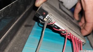
Implementation of this interface on battery:

LV 14S 180A Li from Kona with JKBms 150A and Can interface

View attachment 160382

HV 23S / module 60A from Kona with JK Activ Balancer and Can interface

View attachment 160383

JK - Victron

View attachment 160384

JK - Growatt

View attachment 160385

JK - Sungrow

ONLY 10 Pics for post SORRY!

IF U WANT TECH SUPPORT JUST WRITE TO ME, OR WHATUP!
I am just starting my research for options on how to view and adjust specific BMS settings (and possibly EG4 or other All In One equipment) over a remote Internet connection. I wonder about what specific hardware & PC software are current options. Hope this thread might point to my future research arena. ... I will come back to this thread later for study (just glimpsed it). Any clues for my curiosity side will be appreciated ???⛵?
 
Back
Top