diy solar

diy solar

Can I recharge LifePo4 cells Individually in a 4S pack?

Bhupinder

New Member
Joined
Nov 19, 2019
Messages
113
Hi,
Have this thought going please suggest your opinion.
Do you think Individually recharging Lifepo4 prismatic cells using separate small chargers could work?

This could give a tighter control on charge parameters without the need for a specialized BMS???
Since Potential difference between each subsequent link is same, so in theory if 3.65 V be applied
on cell terminals individually it should charge the whole pack.

What do you say? Has anyone tried it already?

Regards
 
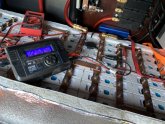
Yes, definitely feasible. I use a rc hobby charger to top off or discharge individual cells that are way out of balance. One word of caution when using multiple chargers simultaneously: Cheaper chargers may have inadequate isolation between their input voltage source and their output.

hitec.jpg
 
Yes, definitely feasible. I use a rc hobby charger to top off or discharge individual cells that are way out of balance. One word of caution when using multiple chargers simultaneously: Cheaper chargers may have inadequate isolation between their input voltage source and their output.

View attachment 9434
Thanks for your valuable feedback.
Yours look like a substantial Installation.
Next Issue I see is limited energy that you can pump through a small Charger @ 3.65 Volts. Would need a lot of them?
 
Have got a few of them lying around, wanna give them a try @3.65V before pepping them up to 14.1V
and placing them in parallel without a BMS.
Albeit had ordered a cheap BMS ($11 150 Amps Separate Port) for testing, but not sure if this particular piece is behaving absurd
or that's the norm, but when connected with an external charger it starts to output fluctuating Cell voltages, like kind of spiking them
in Increasing order with 50ms difference.

I think system is better off without surprises.
Thanks.
 
Okey,
here's some update on the experiment.
For sake of quick charging utilized some of the small dc-dc buck converters lying around.
Set 4 of them in parallel, matched voltages to 14.0V and left them to charge the pack overnight.
In the morning Voltages of all cells were in comparable range of 3.35v - just that one on far -ive end shot upto 3.9v mark
- Bringing pack voltage to 14v, thats probably where it would have stopped charging any further.

So looks, like cells accept charge upto 3.35v fairly easy and beyond that there is internal resistance.
Thinking of charging them individually @3.5v to avoid similar incidents of overcharge in the future.

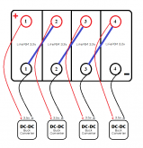
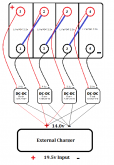
Invite suggestions on tentative connection diagram indicated below:
1585499245465.png
Each buck converter to supply 3.5v on terminals of respective cell.

Now the BIG question is: Could this arrangement work as cells are connected in a string
and could applying voltage on successive poles result in something entirely unexpected?

Electrical engineers, please pour in your valuable advice.

Thanks!
 
@BiduleOhm
Doesn't seem working as we thought it would.
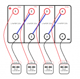
Applying same 3.5v voltages on successive poles causes wires to heat up fast, on checking it looks like the Potential at each terminal rises with rerefence to the first battery terminals. So its not just the successive increase of 3.5v instead its a cumulative increase of voltages at each junction.


Something like this:
1585557311264.png


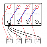
So now looks like we would either have to do a common negative for the pack and apply incremental voltages
of 3.5/7.0/10/5/14v to successive positive terminals or maintain separate negatives along with positive terminal
for each cell - but still voltages needs to be cumulative of the battery position.

Which one does looks better of the two?
1585557768258.png
 
Are those DC/DC converters of the isolated type?

Yes, they are small isolated buck converters - powered by an external common 14V supply.
What are your thoughts?

Any One?? Please share your thoughts. All are Good!!
 
Last edited:
What are your thoughts?

That they aren't isolated... or the wiring don't match the schematic.

Can you measure the resistance between the input negative and the output negative, ideally in both directions, with a DMM?
 
Checking resistance between Negatives of Input and Output terminal of the Buck converter - DMM says "0" Ohms.

Here's the schematic arrangement that was in place at the time of testing:
1585588847200.png

Understandably Voltage diff. @P1-N1 was 3.5 (The Cell voltage)
N1-P2 was small (may be cause they are directly linked).
Now connecting +ive of the second supply @ 2P the wires heated quick - cause PD between the two was ~3.5v.
However PD between -ive of the second supply and 2P was small (May be isolated offset >.02v ),
but then that configuration would leave PD between 2N and Positive of the second supply to be ~6.5v.
- so clearly its can't be done with a 3.5v supply, iti should be increased to ~7.0v for cell to charge.

May be we should combine -ives of all buck supplies to the main negative of the battery pack and supply incremental voltages to each +ive terminal of subsequent cells.


Does it make any sense, or did I managed to confuse it nicely?:ROFLMAO:
 
I do not understand why that is not working.

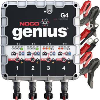
NOCO has a 48V charger I have been using that charges each 12v battery individually. I've been using it for 3 years now.

I believe cause these 4 cells are not isolated as the batteries in your case.
They are tied in a "4S" string and are governed by relative Potential difference at each junction.
May be thats why we need to come-up with a common -ive or +ive reference and then supply required voltages.

Just a guess, but then its upto the electrical engineers to decipher it further.
I don't disconnect the 48V setup. I just put each of the 4 banks on one of the individual "12V" batteries. I dunno. :(
 
Back
Top