diy solar

diy solar

Can Someone please explain the math to actual amps being pulled from the battery to an inverter?

At this point you are just being argumentative just for the sake of it.
How do you get a short at one of the 4/0 wires? They have insulation over them

I’m confused by these statements!

I use 1024 fuses or maybe just 256 breakers in my setup because I cannot predict a fault but I CAN assume the probable outcome of a fire. (hyperbole)

How does a short happen at a 4/0 cable that’s insulated? I have no idea but it doesn’t even matter when I have fuses on the battery terminals.

I’m actually a bit horrified at the question because
How do you get a short at one of the 4/0 wires? They have insulation over them. They are bolted to the MRBF at one end with a rubber boot over it and to the bus bar at the other.
implies there is no point to Fusing in the first place.

That’s how I read it.
 
I’m confused by these statements!

I use 1024 fuses or maybe just 256 breakers in my setup because I cannot predict a fault but I CAN assume the probable outcome of a fire. (hyperbole)

How does a short happen at a 4/0 cable that’s insulated? I have no idea but it doesn’t even matter when I have fuses on the battery terminals.

I’m actually a bit horrified at the question because

Which part of what I said confuses you? I started with a MRBF at the battery terminal covering to the bus bar and a class T to the inverter/SCC. The SCC being covered by breakers and SPD. All wires and bus bars covered by protection device.

btw if you haven't seen it, some pretty cool visuals as a MRBF blows from dead short massive current.

 
Last edited:
Which part of what I said confuses you? I started with a MRBF at the battery terminal covering to the bus bar and a class T to the inverter/SCC
You ‘cover’ the lighter duty load with the Class T but have the potential mass-dump with the lighter duty fuse?

The part that confuses me is where you don’t factor that the fuses perform a loaded-current breaking function that will likely never occur without factoring for “some unseen failure” with ~10,000A of discharge that could turn the bat cables into a massive sustained road flare. Likely not to happen yet if something like even a mouse created an event you are much more vulnerable to fire.

I’ve never blown a Class T thankfully but the downstream fuses have been function-tested a few times.

I’m not afraid of my system and that’s partly due to the fact that it’s planned fail safe. It’s protected against the normal things, while also protecting from the abnormal things we can’t predict. Like 4/0 cables going plasma (2/0 in my case) or whatever else like done Chinesium thing failing in a suboptimal fashion. “How can an insulated cable short?” I dunno, but I’d like my walls to remain should that occur.

So, educate me and tell me how you would lay out the fuses in this system?

Note - that isn't me being a smartass - that is me wanting to understand if there is something I am doing wrong?
 
Last edited:
Where exactly do you think the power in this system is coming from?

A dropped tool across the bus bars would pull 28000 amps and blow all 4 MRBF fuses. A battery going south and dumping current would blow its own fuse. If the SCC went crazy they would pop their breakers. This is off grid so no charging from the inverters.

A short at the inverter wire could pull all the battery amps and the SCC amps. It would pop the class T and the breakers and maybe MRBF.

Wires only vaporize when they receive enough joules of energy to melt them and then convert to gas. Been a long time since chemistry, but that is a lot of energy for 4/0 wire, let alone a length of it. The fuses will all pop long before that happens. If they don't pop you have an entierly different problem. If there is an arc big enough to sustain current and overcome the aic of the fuses it will start by burning the crap out of the loose end and starting a fire.


Not properly installed MRBF with all contact points covered.


I realize this is a lot to read, but the results are really worth it if you think about it - especially you Dadoftheturkeykids given where you have your setup.


I was worried that my hasty calculations were wrong from yesterday so I redid them using 1 meter of cable -- and my old college chemistry/physics book

1 meter of 2/0 contains 0.611714kg of pure copper
Assuming 25c (room temp) to 105c where the insulation melts = 80c

Q (energy in joules) = mass * specific heat of copper * delta T
Q = 0.611714kg * 385 J/kg * 80c = 18813.1784J

Next ohms per meter is 0.0002426 for copper 2/0 welding wire.

power = current^2 * resistance Watts = i^2*r
Energy (joules) = power * time

P = 800a^2 * 0.0002426 ohms = 800a^2 * 0.0002426 ohms = 154.04W
T = 18813.1784J / 154.88W = 121.42 seconds

So in reality it would take 2 minutes at 800amps to get the wire hot enough to start melting insulation

Now I will assume 7000amps from each battery in the case of a dead short across all of them feeding back into one of the 2/0 wires

W = 28000a^2 * 0.0002026ohms = 158844W
t = 18813.1784J / 158844W = 0.1184 seconds

Now - MRBF fuse blow time from the mfg spec sheet - at 600% of rated current or 1200amps for this example
lists between 0.01 and 0.10 seconds

Now - since I have all the numbers I ask myself - how hot will the wire get in the 0.01s and 0.1s

P = 158844W (taken from above as the power of 28000amps)
t = 0.01 seconds from the chart
W = 158844 * 0.01 = 1588.44J

Now go back through the specific heat equations and you will get 6.75c temp rise -

so the wire starting at 25c (77F) will be 31.75c - Or 89.15F
Not even enough temp rise to get the wires warm before the fuses blow on all the batteries

Same equation but for 0.10 seconds = 25c + 49.74c = 74.74c == 166F
now the wire is to hot to touch but this is the long window and no fires started


Now the real MRBF have all blown


And in 1 second the wire would be 522.39c or 970F
Now we have a blazing fire if the wire is run any place that can catch anything nearby.

Melting point of copper is 1984F or 1085c --
It takes 2.13 second at 28000a to reach this point.
At 800 amps it takes 24 minutes.

If the fuse fails to blow we have a fire 🔥 super quick. With cheap no-name fuses this could happen. Now I expect any sort of fuse to blow sometime between to hot to handle and open flames and melted wires.

I personally didn't expect that result. Now from the shape of the curve the time gets shorter as the current goes up but in a LOG fashion.

What this tells me is all the wires between the batteries and the inverter should be inside metal conduit. For me at least it is eye opening.

This is why I check my work the next day - am but an egg (stranger in a strange land reference)

Now that I am all humbled by the numbers, I am really really interested in what you have to say, both of you.
 
Last edited:
I appreciate all the help and the numbers (albeit a little confusing to me), and concern as all my testing has been with a simple multimeter and my own hand touching and feeling every connection and wire. I still have the cheapo 200amp breaker in between my battery bank and inverter, and when I have tried to pull 1500 watts it pops, which is relieving but definitely a concern of mine to replace, because I do feel it heat up in that circumstance. For now I stay under 1kw, just running some lights, my t.v., fridge and furnace. I would like to note that all my wiring is 4/0 for battery connections and inverter. Between my scc's and batteries is 6awg with 50amp breakers and 32amp breakers going to my 40amp scc's. I do err on the side of caution hence I put breakers on everything and oversized all my cabling. I think putting metal housing on all my wiring may introduce a whole other can of worms susceptible to a short occurring, as you have said in a worst case scenario each battery is capable of putting out 7000amp in a very short time frame, I think decorating the whole setup with conductive metal all over the place seems quite scary.

On another note I think a 350amp class-t might fit my usage. But before I blow a $60 fuse just testing, is there anything wrong with me trying a couple cheap ANL fuses first just for testing purposes? Also will and ANL fuse fit in a class-t fuse block?

Thank you guys for all the help, and even the off-topic discussion/disagreements I find very enlightening and educational.

Thanks

The point of all of it is to say if you have the MRBF on the posts of your batteries and you get a short your wires will get anywhere between a little warm and to hot to touch.

In your current configuration if you get a short and those cheap lever arm breakers don't work you will have a blazing fire in 2 minutes or so.


So I hope your install is no longer in your bedroom or a place where it can catch your house. Ideal would be in an outbuilding or disonnected until you get fuses in place
 
I appreciate all the help and the numbers (albeit a little confusing to me), and concern as all my testing has been with a simple multimeter and my own hand touching and feeling every connection and wire. I still have the cheapo 200amp breaker in between my battery bank and inverter, and when I have tried to pull 1500 watts it pops, which is relieving but definitely a concern of mine to replace, because I do feel it heat up in that circumstance. For now I stay under 1kw, just running some lights, my t.v., fridge and furnace. I would like to note that all my wiring is 4/0 for battery connections and inverter. Between my scc's and batteries is 6awg with 50amp breakers and 32amp breakers going to my 40amp scc's. I do err on the side of caution hence I put breakers on everything and oversized all my cabling. I think putting metal housing on all my wiring may introduce a whole other can of worms susceptible to a short occurring, as you have said in a worst case scenario each battery is capable of putting out 7000amp in a very short time frame, I think decorating the whole setup with conductive metal all over the place seems quite scary.

On another note I think a 350amp class-t might fit my usage. But before I blow a $60 fuse just testing, is there anything wrong with me trying a couple cheap ANL fuses first just for testing purposes? Also will and ANL fuse fit in a class-t fuse block?

Thank you guys for all the help, and even the off-topic discussion/disagreements I find very enlightening and educational.

Thanks

Nothing wrong with testing with cheap stuff at all.

In your case though, I would consider going 48Volt.

You'll eliminate the need for lots of those expensive and time consuming bus bars, extra cables, cable holders, fuses etc.

All that stuff adds up quick and can take a lot of time to lay out properly.

IMO, of course.
 
I realize this is a lot to read, but the results are really worth it if you think about it - especially you Dadoftheturkeykids given where you have your setup.


I was worried that my hasty calculations were wrong from yesterday so I redid them using 1 meter of cable -- and my old college chemistry/physics book

1 meter of 2/0 contains 0.611714kg of pure copper
Assuming 25c (room temp) to 105c where the insulation melts = 80c

Q (energy in joules) = mass * specific heat of copper * delta T
Q = 0.611714kg * 385 J/kg * 80c = 18813.1784J

Next ohms per meter is 0.0002426 for copper 2/0 welding wire.

power = current^2 * resistance Watts = i^2*r
Energy (joules) = power * time

P = 800a^2 * 0.0002426 ohms = 800a^2 * 0.0002426 ohms = 154.04W
T = 18813.1784J / 154.88W = 121.42 seconds

So in reality it would take 2 minutes at 800amps to get the wire hot enough to start melting insulation

Now I will assume 7000amps from each battery in the case of a dead short across all of them feeding back into one of the 2/0 wires

W = 28000a^2 * 0.0002026ohms = 158844W
t = 18813.1784J / 158844W = 0.1184 seconds

Now - MRBF fuse blow time from the mfg spec sheet - at 600% of rated current or 1200amps for this example
lists between 0.01 and 0.10 seconds

Now - since I have all the numbers I ask myself - how hot will the wire get in the 0.01s and 0.1s

P = 158844W (taken from above as the power of 28000amps)
t = 0.01 seconds from the chart
W = 158844 * 0.01 = 1588.44J

Now go back through the specific heat equations and you will get 6.75c temp rise -

so the wire starting at 25c (77F) will be 31.75c - Or 89.15F
Not even enough temp rise to get the wires warm before the fuses blow on all the batteries

Same equation but for 0.10 seconds = 25c + 49.74c = 74.74c == 166F
now the wire is to hot to touch but this is the long window and no fires started


Now the real MRBF have all blown


And in 1 second the wire would be 522.39c or 970F
Now we have a blazing fire if the wire is run any place that can catch anything nearby.

Melting point of copper is 1984F or 1085c --
It takes 2.13 second at 28000a to reach this point.
At 800 amps it takes 24 minutes.

If the fuse fails to blow we have a fire 🔥 super quick. With cheap no-name fuses this could happen. Now I expect any sort of fuse to blow sometime between to hot to handle and open flames and melted wires.

I personally didn't expect that result. Now from the shape of the curve the time gets shorter as the current goes up but in a LOG fashion.

What this tells me is all the wires between the batteries and the inverter should be inside metal conduit. For me at least it is eye opening.

This is why I check my work the next day - am but an egg (stranger in a strange land reference)

Now that I am all humbled by the numbers, I am really really interested in what you have to say, both of you.


So, @Checkthisout

First, my apologies, you were right.
What do we do? 1 second from disaster? Do we fuse both ends of every cable?

@Dadoftheturkeykids

Sorry I hijacked your thread, I only meant to help


There are three failure modes of the BMS I can think of -
1. The BMS senses the short and shuts down after a moment of very high current
2. The BMS fries and makes magic smoke then current is cut
3. The BMS fries and makes magic smoke and then melts with current ON

And
4. The BMS work and limit current to 200amps - but does it react fast enough?

One thing that came up when thinking about it - It depends on where in the cable the short was as to how high the heat generated is.

If the short happens 1 inch from the bus bar
The Bus bar heats some, but is spec'd to 1000amps so is safe
The end next to the bus bar doesn't actually heat much even though it has 600amps through it because the resistance of 1 inch is so tiny it may as well be an extension of the bus bar at this point.
The end from the battery has 200amps through it and it is producing 8~10 watts over its length

What about the wrench - assuming the BMS limit current to 200amps each
The point of contact will have the full 800amps through it and it is probably not the best contact so high resistance. The wrench is make of steel and assume it is 8 inches long. The point of contact will be plasma and a contact arc with a temperature over 10,000C is what the website I looked it up on tells me. At this point either the wrench is blown away from the contact or it welds in place. Here is what happens if it welds in place. Steel is not the best conductor.

(going to skip the calculations)

At 5 seconds the wrench is 532C or 971F.
At 10 seconds it is 1064C or 1919F.
At 15 seconds it is at 1596C or 2879F.

It is between 10 and 15 seconds that the wrench melts (around 1450C)

So the conclusion from this is if the BMS limit to 200amps it isn't the wires melting that will get you, it is the wrench melting.


If the BMS all let through a full 7000amps per battery though the system -
The wrench hits melting metal at 0.0036 seconds and the 2/0 has melted at 0.0027 seconds.... which means you have melted copper and steel flying around and no amount of protection will save you because none of it acts quick enough. This is why they have you wear safety gear when around high amperage.


So the moral of the story is:
A - don't design a system where it is possible to drop a wrench across the poles or have the wires shorted like the referenced failure story
B - make sure to cover and shield everything
C - Use insulated tools - fully insulated
D - Protection devices - Fuses and breakers - use quality ones at the right places

The right places are as close to the source of power as possible - i.e. on the posts --- and


@Checkthisout - this is your queue - because I am just an egg and now realize I just don't know the answer
The other right place??????? at the bus bar?
 
Last edited:
definitely a concern of mine to replace, because I do feel it heat up in that circumstance
It’s not the heat (resistance) per se- it’s the successful breaking of the arc; with lithium that arc can be in Teslacle proportions. Or is that biblical proportions?
 
So, @Checkthisout

First, my apologies, you were right.
What do we do? 1 second from disaster? Do we fuse both ends of every cable?

@Dadoftheturkeykids

Sorry I hijacked your thread, I only meant to help


There are three failure modes of the BMS I can think of -
1. The BMS senses the short and shuts down after a moment of very high current
2. The BMS fries and makes magic smoke then current is cut
3. The BMS fries and makes magic smoke and then melts with current ON

And
4. The BMS work and limit current to 200amps - but does it react fast enough?

One thing that came up when thinking about it - It depends on where in the cable the short was as to how high the heat generated is.

If the short happens 1 inch from the bus bar
The Bus bar heats some, but is spec'd to 1000amps so is safe
The end next to the bus bar doesn't actually heat much even though it has 600amps through it because the resistance of 1 inch is so tiny it may as well be an extension of the bus bar at this point.
The end from the battery has 200amps through it and it is producing 8~10 watts over its length

What about the wrench - assuming the BMS limit current to 200amps each
The point of contact will have the full 800amps through it and it is probably not the best contact so high resistance. The wrench is make of steel and assume it is 8 inches long. The point of contact will be plasma and a contact arc with a temperature over 10,000C is what the website I looked it up on tells me. At this point either the wrench is blown away from the contact or it welds in place. Here is what happens if it welds in place. Steel is not the best conductor.

(going to skip the calculations)

At 5 seconds the wrench is 532C or 971F.
At 10 seconds it is 1064C or 1919F.
At 15 seconds it is at 1596C or 2879F.

It is between 10 and 15 seconds that the wrench melts (around 1450C)

So the conclusion from this is if the BMS limit to 200amps it isn't the wires melting that will get you, it is the wrench melting.


If the BMS all let through a full 7000amps per battery though the system -
The wrench hits melting metal at 0.0036 seconds and the 2/0 has melted at 0.0027 seconds.... which means you have melted copper and steel flying around and no amount of protection will save you because none of it acts quick enough. This is why they have you wear safety gear when around high amperage.


So the moral of the story is:
A - don't design a system where it is possible to drop a wrench across the poles or have the wires shorted like the referenced failure story
B - make sure to cover and shield everything
C - Use insulated tools - fully insulated
D - Protection devices - Fuses and breakers - use quality ones at the right places

The right places are as close to the source of power as possible - i.e. on the posts --- and


@Checkthisout - this is your queue - because I am just an egg and now realize I just don't know the answer
The other right place??????? at the bus bar?

Fuse at the bus bar and battery with total fusing no larger than what it takes to protect the smallest conductors or limiting point in your system.

The BMS is a fuse/breaker. If we are using batteries that have a BMS, then just use the overcurrent protection on the BMS as the fuse AND fuse at the bus bar and make sure the sum of all the BMS overcurrent protection does not exceed that which will protect the largest conductor.


In the case of the OP, he should change to 48 Volts and avoid this conversation all altogether. A 48V system and server rack battery will net the same capacity as 4 12V batteries as the OP shows.
 
On another note I think a 350amp class-t might fit my usage. But before I blow a $60 fuse just testing, is there anything wrong with me trying a couple cheap ANL fuses first just for testing purposes? Also will and ANL fuse fit in a class-t fuse block?
That is an ancillary benefit to fusing the batteries with Class T: properly fused they will never probably blow anyways. Then the actual loads are individually fused with ANL (in my case). Although I do occasionally argue with myself that the loads theoretically could stay closed through a plasma arc, though I don’t believe that is much of a practical risk.
 
Fuse at the bus bar and battery with total fusing no larger than what it takes to protect the smallest conductors or limiting point in your system.

The BMS is a fuse/breaker. If we are using batteries that have a BMS, then just use the overcurrent protection on the BMS as the fuse AND fuse at the bus bar and make sure the sum of all the BMS overcurrent protection does not exceed that which will protect the largest conductor.


In the case of the OP, he should change to 48 Volts and avoid this conversation all altogether. A 48V system and server rack battery will net the same capacity as 4 12V batteries as the OP shows.

I hear you on this one, I wouldn't start at 12v again unless it was very specific use case and only 1 battery involved. He already has the batteries so is kinda stuck with it unless he puts them in series with an active balancer.

As for the BMS being a fuse/breaker there are a number of other threads talking about that subject - I haven't finished enough to tell what the verdict is but it seems to be leaning heavy into not trusting it to do the job quick enough

That is an ancillary benefit to fusing the batteries with Class T: properly fused they will never probably blow anyways. Then the actual loads are individually fused with ANL (in my case). Although I do occasionally argue with myself that the loads theoretically could stay closed through a plasma arc, though I don’t believe that is much of a practical risk.

Looking at the failure curves of the class T fuses they seem to start at 0.01 and extend all the way to 1 second even when at 200% of rated current. The earlier math shows that we could easily have a fire in the time it takes the class T to blow. They are refered to as "fast fuses" but in reality looking at the curves in the mfg documents they are only a tiny tiny bit better than the MRBF. i.e. they are 0.01sec at 400% verse 0.01sec at 600% on the curve. But tiny fractions of a second make a huge difference so I may have to work that math and see what it says and if it makes sense to use the expense of a class T verse MRBF or other type fuse (don't worry I won't do it here).


So that leaves us with the response times on the BMS which I haven't investigated yet. But if they clamp the current to max fast enough without failing shorted that may actually make things worse at the fuse since the time to fail at rated current verse at a fault current of 600% is enough longer that you melt the wires/wrench. I _hope_ the designers of BMS take a failure into account and design for failing open.


And now thinking through what @Checkthisout said - if the batteries are fused at the bus bar - you drop a wrench across any individual wire to the neg bus bar - it will blow the fuse for that single wire and have a much longer time to heat the wrench and wire at 200amps until the BMS shuts down. Will have to lookup how long BMS take to fail if I can find it and trust it. BUT, it seems suspect since I keep reading these batteries can fail when shorted with 7000amps. I wonder if that is real world measurement or if that is something everyone repeats because they have read/heard it.

NOTE - I started to type "When you drop a wench on the bar" ... then I fixed it.

Fusing for smallest conductors - At first I took this to mean wiring all different loads to the same size as the largest conductor but in this case it means you fuse the wire to the load at the bus bar and use a fuse/wire matched to the expected load.


Lead a horse to water.... eventually I am smart enough to learn something once I get past what I think I know
 
Last edited:
As for the BMS being a fuse/breaker there are a number of other threads talking about that subject - I haven't finished enough to tell what the verdict is but it seems to be leaning heavy into not trusting it to do the job quick enough

I think it can provided it's a quality BMS.

Looking at the failure curves of the class T fuses they seem to start at 0.01 and extend all the way to 1 second even when at 200% of rated current. The earlier math shows that we could easily have a fire in the time it takes the class T to blow. They are refered to as "fast fuses" but in reality looking at the curves in the mfg documents they are only a tiny tiny bit better than the MRBF. i.e. they are 0.01sec at 400% verse 0.01sec at 600% on the curve. But tiny fractions of a second make a huge difference so I may have to work that math and see what it says and if it makes sense to use the expense of a class T verse MRBF or other type fuse (don't worry I won't do it here).


So that leaves us with the response times on the BMS which I haven't investigated yet. But if they clamp the current to max fast enough without failing shorted that may actually make things worse at the fuse since the time to fail at rated current verse at a fault current of 600% is enough longer that you melt the wires/wrench. I _hope_ the designers of BMS take a failure into account and design for failing open.


And now thinking through what @Checkthisout said - if the batteries are fused at the bus bar - you drop a wrench across any individual wire to the neg bus bar - it will blow the fuse for that single wire and have a much longer time to heat the wrench and wire at 200amps until the BMS shuts down. Will have to lookup how long BMS take to fail if I can find it and trust it. BUT, it seems suspect since I keep reading these batteries can fail when shorted with 7000amps. I wonder if that is real world measurement or if that is something everyone repeats because they have read/heard it.

NOTE - I started to type "When you drop a wench on the bar" ... then I fixed it.

Fusing for smallest conductors - At first I took this to mean wiring all different loads to the same size as the largest conductor but in this case it means you fuse the wire to the load at the bus bar and use a fuse/wire matched to the expected load.


Lead a horse to water.... eventually I am smart enough to learn something once I get past what I think I know

I'll try and draw a picture later, to make it easier to discuss.
 
I am trying to size a class-t fuse for my offgrid setup.

My inverter is 3000w continuous+ surge
I will only be pulling 2400 continuous at any given time but I want my fuse to cover up to 3000watts.

I understand that power out is not equivalent to power in, because of conversion losses.

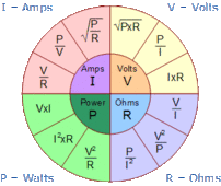
Can someone please explain the formula to find what amperage is being drawn from my batteries @ 3000watts?
Formulas from Ohms law:


dccircuits-dcp4 (1).gif
 
This isn't useful when sizing a fuse and type for an inverter because surge values vary based on manufacturer and model as well the fact that many inverter manufacturers do not provide a VA rating, only wattage.
Since when did ohms law become obsolete?
Wattage is a measure of power.
Everyone knows that fuses should be sized higher than power (wattage).
The previous posters made this fact clear.
 
The questioner requested formulas.
Could you please provide your formula?

And do it as a function of manufacturer, model number and wattage please?
And do it with no refference to Ohms law.
 
Last edited:
Back
Top