diy solar

diy solar

Can Someone please explain the math to actual amps being pulled from the battery to an inverter?

So, looked up the JK BMS and it appears they are using the HYG023N04LS1D mosfet -

data sheet https://xonstorage.blob.core.windows.net/pdf/huayi_hyg023n04ls1d_apr22_xonlink.pdf

Seems like the response time from on to off is 33ns ... even if they do a not great job of switching/monitoring that it is more than fast enough to protect the wire. (0.000000033 seconds)

Which comes down to the good quality verse cheap quality BMS... this would be in design, component, potting, and heatsink. If you figure it might be a way to save a few cents to leave out a few mosfet - they are strung in parallel to reach the current rating on the BMS with a few extra for safety margin. Now we can assume the cheaper end BMS will cut corners and the cheaper battery mfg will cut the same corners. The question is would those cut corners make a difference?

In the case of the LiTime batteries (the type the OP is using) and brand so far everything I have seen from them is done right and very good quality even when it would be possible to cut a corner and make things cheaper. So I would trust them for this at least that they wouldn't cut the corner enough to be dangerous.

So I am with Checkthisout and a fuse at the bus bar is good to protect the wires from the batteries and use the BMS as the fuse/protection at the other end.


So what about cheaper brands and low quality no-name BMS? Drop off a few mosfets and have just enough capacity to do the job with nothing to spare and run everything at max. Turn one down or off because of a surge in current? or overheat a few?

In my hazel past it seems like when fets are overcurrent or overtemp they tend to fail shorted - sometimes with an exploding sort of result if the PSU behind it melts the junction and then the silicone fractures the case.

Do we as a collective group have a history of how BMS tend to fail when there is enough of it left to look at?
 
The questioner requested formulas.
Could you please provide your formula?

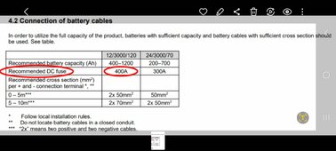
1) Look at the page in the owners manual that says what size and type of fuse to use.

Using your formula, we would end up using a 200 amp fuse on our 24 volt model, rather than the 300 amp the manufacturer specifies.


Screenshot_20240325_120405_Gallery.jpg
 
Using your formula, we would end up using a 200 amp fuse on our 24 volt model, rather than the 300 amp the manufacturer specifies.
It's not my formula. It was developed by German physicist Georg Ohm in 1827.
I'm sure the designers of those inverter specs you posted used it in determining the recommended fuse size.
Do you think they do it by trial and error?
 
It's not my formula. It was developed by German physicist Georg Ohm in 1827.
I'm sure the designers of those inverter specs you posted used it in determining the recommended fuse size.
Do you think they do it by trial and error?

I can see you're frustrated.

Determining Inverter fuse size can be that way given the different surge capabilities and rating systems manufacturers use when making output claims for their given Inverter.

That's why it's best to simply refer to owners manual and make sure you're purchasing a quality Inverter from a manufacturer who actually specifies the fuse size in their manual.

If only it were as easy as using ohms law, that would be nice.
Ohms law also works on the surge current capacity.
Anyone working on solar better at least know ohms law.
 
Ohms law also works on the surge current capacity.
Anyone working on solar better at least know ohms law.

Victron specifies a 400 amp fuse for their 12/3000 inverter.

It surges to 6000 watts.

If we did it the way you and @MisterSandals said we would end up:

6000/10.5 = 571 amps. We would then have a 600 amp fuse installed where the manufacturer specifies 400. 😲
 
Don't compute fuse size based on surge current. Use max continuous current.
Check fuse curve, likely 2x surge is good for minutes, vs. inverter can only sustain for seconds.

That's why it's best to simply refer to owners manual and make sure you're purchasing a quality Inverter from a manufacturer who actually specifies the fuse size in their manual.

SMA says to use max 56A OCP on output of Sunny Island, which can pass through 56A.
That doesn't allow derating for 80% continuous. Best I could come up with is 60A Midnight/CBI magnetic-hydraulic breaker, which is guaranteed no trip below 105%, 63A.

But mostly, I just ignore that part of the manual. I protect input with 70A thermal-magnetic, or 60A magnetic-hydraulic.

Surge current (e.g. double for 3 seconds, 180A for milliseconds), I don't worry about. The 180A should work to trip 20A, possibly 30A breaker. Surge starts motors but OCP provides enough time delay to not trip.
 
Don't compute fuse size based on surge current. Use max continuous current.
Check fuse curve, likely 2x surge is good for minutes, vs. inverter can only sustain for seconds.

I don't. I just let the manufacturer specify the fuse as there are a lot variables with inverters that anyone but the engineers can't know.


SMA says to use max 56A OCP on output of Sunny Island, which can pass through 56A.
That doesn't allow derating for 80% continuous. Best I could come up with is 60A Midnight/CBI magnetic-hydraulic breaker, which is guaranteed no trip below 105%, 63A.

But mostly, I just ignore that part of the manual. I protect input with 70A thermal-magnetic, or 60A magnetic-hydraulic.

Surge current (e.g. double for 3 seconds, 180A for milliseconds), I don't worry about. The 180A should work to trip 20A, possibly 30A breaker. Surge starts motors but OCP provides enough time delay to not trip.

In that case, I would contact the manufacturer and make them specify an exact part# for the component they want you to use.
 
The problem is that ohms law doesn't account for everything.

You can figure the rough current no problem. What you can't figure in is how long the surge is good for? How much extra current will it pull during a max surge? Depending on the build quality the answer for fuse type/size is not a simple thing - which is why our irritating friend is saying RTFM. (Yes he irritated me until I did the math and realized he is right, now I agree with him.... I say him, but it could be a her or they and I wouldn't care).

So seeing as how the manual I found doesn't list a surge current duration but other similar inverters do I can assume that it would use double the current for 1~5 second or 150% for 20 seconds or 120% for 40 seconds... it is a pretty steep curve. ... then you compare that to the fuse curves that match so you don't get a blown fuse for no reason other than you turned on a microwave... Or you can RTFM where it tells you the size to use. and see if it makes sense
 
Don't compute fuse size based on surge current. Use max continuous current.
Check fuse curve, likely 2x surge is good for minutes, vs. inverter can only sustain for seconds.


SMA says to use max 56A OCP on output of Sunny Island, which can pass through 56A.
That doesn't allow derating for 80% continuous. Best I could come up with is 60A Midnight/CBI magnetic-hydraulic breaker, which is guaranteed no trip below 105%, 63A.

But mostly, I just ignore that part of the manual. I protect input with 70A thermal-magnetic, or 60A magnetic-hydraulic.

Surge current (e.g. double for 3 seconds, 180A for milliseconds), I don't worry about. The 180A should work to trip 20A, possibly 30A breaker. Surge starts motors but OCP provides enough time delay to not trip.


Now I have to lookup OCP and CBI magnetic-hydraulic breaker to see what they are and how they work.... thanks, more homework
 
The problem is that ohms law doesn't account for everything.

You can figure the rough current no problem. What you can't figure in is how long the surge is good for? How much extra current will it pull during a max surge? Depending on the build quality the answer for fuse type/size is not a simple thing - which is why our irritating friend is saying RTFM. (Yes he irritated me until I did the math and realized he is right, now I agree with him.... I say him, but it could be a her or they and I wouldn't care).

So seeing as how the manual I found doesn't list a surge current duration but other similar inverters do I can assume that it would use double the current for 1~5 second or 150% for 20 seconds or 120% for 40 seconds... it is a pretty steep curve. ... then you compare that to the fuse curves that match so you don't get a blown fuse for no reason other than you turned on a microwave... Or you can RTFM where it tells you the size to use.
I believe what you mean is: ohms law doesn't account for everything when determing fuse size or type for an inverter.
I totally agree. I was merely answering the posted question, that no one else seemed to have answered at that point in the thread.
I have no issues with the plethora of responses regarding fuses, surge protectors delay times and the like.
And as much as I hate to admit it, checkthisout's response that using the manufacturers specs is probably the safest way to go, but that wasn't the question posted.
 
Victron specifies a 400 amp fuse for their 12/3000 inverter.

It surges to 6000 watts.

If we did it the way you and @MisterSandals said we would end up:

6000/10.5 = 571 amps. We would then have a 600 amp fuse installed where the manufacturer specifies 400. 😲
The 400 amp fuse better be able to handle 600 amps for a short duration of time.
 
I believe what you mean is: ohms law doesn't account for everything when determing fuse size or type for an inverter.
I totally agree. I was merely answering the posted question, that no one else seemed to have answered at that point in the thread.
I have no issues with the plethora of responses regarding fuses, surge protectors delay times and the like.
And as much as I hate to admit it, checkthisout's response that using the manufacturers specs is probably the safest way to go, but that wasn't the question posted.
Well if you want to take it to that then what I meant was it doesn't account for everything, we need the unified field theory to do that and even that is in question these days.
 
Now I have to lookup OCP and CBI magnetic-hydraulic breaker to see what they are and how they work.... thanks, more homework


CBI, also Carling Tech. Both relabeled by Midnight.

Magnetic breaker trips instantly when enough current flows, e.g. > 5x rating.
With a magnetic core held back by spring, in silicone oil, at modest overload it moves slowly until it makes field strong enough to trip.

You can find diagrams online.

I think they can protect motors and the like better than thermal overload. Also are not affected by ambient temperature or rise due to electrical connections.

 
Back
Top