diy solar

diy solar

Chargery BMS now with Low Temp Cutoff

Steve_S

Offgrid Cabineer, N.E. Ontario, Canada
Joined
Oct 29, 2019
Messages
7,786
Location
Rural NE Ontario Canada
Good Day Folks !

Note:
I have no affiliation with Chargery whatsoever, I'm just a customer sharing info in the best interest to help others.

I purchased a Chargery BMS8T a month or so ago as a replacement BMS for my ShunBin pack. Post showing installation on ShunBin Pack The installation has been pretty straight forward but one feature the BMS did not have was a Low Temp cutoff. After some discussions with Jason Wang @ Chargery, new firmware has been made... Chargery BMS / Balancer page YES that's right, they can have their firmware updated, unlike most other BMS'. The Firmware can be updated on the main unit to version V1.22, & the LCD unit version to V3.03 which will now support Low Temp Cutoff.
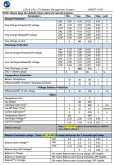
  • Low temp. cutoff in charge -20C min. 20C max.
  • Low temp. cutoff in discharge -20C min. 20C max.
Chargery BMS*T is designed special for LiPo,LiFe and LiTo battery pack applied to storage energy system and
Electrical Vehicle including E-Motorcycle, E-Scooter and so on. The unit can measure or detect the battery voltage,
cell voltage, charge & discharge current, battery temperature, and battery SOC (State of Charge) , displayed with
TFT color LCD.

New Updated Documentation Is being prepared TODAY and the firmware & docs should be posted within the next day or two. (doc's need a bit more polish).

Link to Setup Screen for Low Temp & Table of Features (post 10)

* I've also highlighted the customer desire for BlueTooth / Wifi connectivity as a good bonus to have available. They currently have an RS232 interface which a PC can access but this is not a simple and easy method that many prefer. I cannot be certain if/when such may be available but finger's crossed that they are cooking it up, possibly as an extra small module or something.. I believe if enough people ask for it, that would support having such a feature done quicker.


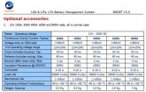
So far, I am quite pleased with the hardware, it all works as expected and easy enough to install & setup, albeit the manuals need clarity so take your time. I chose to use a Deltec 500A/50mv Shunt as opposed to the one supplied by them, not only because the Deltec's have a backing & can be surface mounted, they are Brass Units and calibrated for accuracy. The Heavy Duty N.O. Relays are pretty serious, so I kept those but any High End 12V relay that is rated for the AMPS will work fine if you want to go electronic vs mechanical.

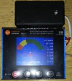
The BMS8T kit as I received it (I purchased directly from Chargery and they expedited shipping and it was great ! )
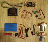
bms8t-kit.jpg

REF for Deltec Shunt:

ARE YOU SEEING RIPPLE ON THE BMS ?
Do you have EMI/RFI ISSUES ??
Are Amps In/Out or Voltages "fluttering" ???
It could be your Wiring Layout !

SEE THIS POST:

 
Last edited:
I did a little customization for my install to "tidy" things up as I am all to aware of Murphy's Laws & things going awry when least expected. I thought I would share the info for others to consider or their own installations.

BMS Remote:
The remote has an external Buzzer & LED for alerts & warnings o 600mm wires. I did not want to deal with loose bits, so I go a small "project box" to put the buzzer & led into (hot glued, so removable) and with a bit of shrink wrap, & double Velcro, voila, nice & tidy and no bits to deal with.
BMS-Control-w-module.jpg

BMS Delay Board:
I also ordered the Delay Board to handle high surges and prevent a cutoff in those instance by allowing a small delay (programmable to 2, 3 or 6 seconds). The board itself has a rubber backing but is exposed and needs to be mounted or something. So again, another project box to put it in and make it wall mountable under the relay set. Keeps things tidy & neat. This also allows me to see the 3 status LEDs on the delay board.
BMS-Delay-Board.jpg

UPDATE: FEB:26:2020
For anyone looking for similar "project boxes" check out this manufacturer below, available in clear & transparent colours. Roughly $6 CAD
 
Last edited:
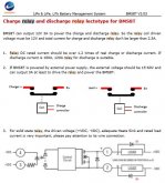
BMS Delay Board information:

relay-controller-jpg.3428


RELAY SPECS from Chargery Docs
RMS-Relay-info.JPG
 
Last edited:
Good job! I'm curious as to how you are using the delay board?
 
Good job! I'm curious as to how you are using the delay board?
In the interim I just wired the relays directly to the BMS without the Delay Board till I get everything setup & dialed in (getting the Deltec Shunt this morning) and then once all wired in I'll be tweaking it in for my loads which I am going to have to step through test. I don't have anything with a super high surge (soft start well pump and such) but there are a couple of things that do have a wee "kick" on start which is where I want to make sure it's set right. The delay board is an option which I felt I better have "just in case" I need it, so I have to test it out for my use.

Their documentation on the delay board is a tad too "direct translated obscure" so it needs a bit of decoding.
 
I think for people wanting to pre-charge there inverter would be a good ad-on.
 
A quicky update:
Jason just advised me they have completed the firmware for the BMS8T series and finishing the preliminary docs, he will be sending that to me tomorrow (January 10) so I can install & set it up. They are 13 hours ahead of me, so the time difference can be challenging to work around. Still having some clarity issues with the docs, hopefully that will be sorted in short order as well.. I also suggested that they may want to send a complete unit to Will Prowse once completed so he can have some fun with it and give us one of his great reviews (make it or break it test, LOL).
 
Great news about the low temp cutoff, hopefully bluetooth or wifi connectivity won't be far behind (though that might be a larger project).

If I recall correctly, you mentioned connecting a Raspberry Pi to the BMS. Have you made any progress on this project, this is something I am very curious about.
 
The plan is to run the Samlex Inverter, the BMS into a USR-IOT RS232/485 to IP / Modbus converter which goes to the router & Raspi. I'm setting up the Raspi with Node-Red, Grafana & InfluxDB as a manager for my Classic, Samlex & BMS. It's a low priority project as I have other beasts to battle ATM.

I did suggest to James that BT/Wifi/Ethernet would be a major selling point as well, possibly incorporated (would be more complicated to do, as it would be a reddesign of the cases etc) or an external add-on module that could plug into the existing ports (which may be easier & cheaper to make happen). They responded & reacted favourably to the Low Temp Disconnect suggestion but then again that was a firmware fix (much easier to do) which surprised me at how fast they acted on it and I see that as a good sign of things...
 
Great news for this low temp cutoff! Thanks for the exchanges you had with the manufacturer and the very prompt improvement of this BMS! I just ordered it then, I was hesitating with the TinyBMS (which had low temp cutoff from the beginning) but now that Chargery caught on, and considering the additional screen and the price, I went for it.

I didn't order the relays that are proposed with it though, according to the datasheet on their website they suck 4 to 10 W, I find it's too much (a quarter to half a kWh per day is burnt just for two relays!). I found rather these "Smart Dual Relays" from the BMS123 company which are bistable latching relays (no need to keep the coils powered all the time) combined with a driver circuit. The driver circuit seems to translate the "close relay" signals that come out of the BMS into the impulsions that are needed to toggle the latching relays. Big advantage is that this relay system consumes only a few mW, but the drawback is that if it looses all power the relays won't go back in a default open position like classic non-latching relays. But unless a wire is cut I don't really see how that would happen. Not sure yet whether they are compatible with a 48V system though, I asked the seller and will report here when I get an answer, until now I have seen conflicting specs about that.
 
@Steve_S
In relation to this 'Chargery' unit...(48v 16S)
I'm not electrical, so steep learning curve for me...please bear with me...
So, if my understanding is correct, the delay board has three relay outputs, which in total cant exceed 2.5A output. In relation to using an 'All in one' inverter/charger unit, if i connected Charge Relay 1/ to the solar panel array disconnect input string (potentially 65v at 19A max ).
Small current Relay 2/ connected to the input 13A 240vAC supply(for when connected to grid supply)
and Large current delayed time Relay 3/ connected to the combined battery/inverter/load input...

such that, on BMS triggering the disconnect signal to the delay module, it immediately disconnects the panel array and AC power inputs, then after so many seconds, it disconnects the battery/inverter/load aspect. Does this successfully avoid the typical inrush currents that damage the inverters? I believe that after the main delayed time relay activates, the other two relays re set themselves anyway. I assume this then protects the battery pack totally until the delay module is switched off again to reset, however long it might take. Have i read this correctly?

I'm still trying to understand the relays.... any problems with any of these associated connections?
Charge Relay 1/... use the 100A version?
Small current Relay 2/ ...use 100A version...ok with AC switching?
Large current 'delayed' time Relay 3/ ....use the 200A version, which would adequately cover the maximum 'peak' draw from the battery bank ?

If relay 2/ is unsuitable because it is switching an AC circuit, could you explain why? If i needed to utilise an opto enabled relay to 'switch' the AC, then so long as it was 12vdc and less than 0.8A in the control side and covered more than 13A on the AC side, then i should be good?

Thanks steve for any experience you might wish to impart, you having used this unit personally, id much appreciate it if you could take the time to explain these aspects. Regards.
I suspect some confusion here. the 12V/3A from the BMS to relay (or delay board) is just to activate the relay itself, to close the contactor. These are NO Contactor relays. the 100A / 200A etc ratings are for the amount of amperage they can pass though when the latch is closed. This is DC ONLY ! The relays should be no less than 1.25 times higher amperage than the max load you expect to go through there. So a 100A throughput should have a min of 125A relay. It is better (read wiser) to go above that to 200A so you never reach the max capacity of what the relay can handle, the alternative could be a melted relay or worse should the tolerance not be accurate.

At present I am tinkering without the Delay Board (I got it for "just in case" I had a loading issue that required a further delay mechanism to deal with surges. The documentation on this feature / function is absolutely atrocious, so I have been trying to clarify that with Jason and to possibly come up with a clear English Translation for their docs, especially on such an important detail.

I am NEW to using this BMS and LFP as I am transitioning from an FLA Bank and expanding from there. So it's been a small learning curve for me to absorb this material as well and have spent far too many hours studying various BMS' and their abilities, capabilities & short comings. I looked at many different ones and considered what would work for me and my particular setup and where I want to take my system and felt that Chargery was the answer for me. Once I have more LFP packs with each having their own BMS then things will get even more deeply interesting.... hoping it's just not deep in manure ! I'm now discovering the "joy's of" making FLA & LFP cohabitate (ohhh what fun, ~not~) but I can't just chuck $3200 worth of FLA because...

PS: Sorry I cannot answer all your questions fully, I'm still getting the hang of these.
Many thanks steve for you input. Appreciated.
Thinking about it logically, i probably dont need to 'relay' the AC supply side as the plug itself is protected by a 13A fuse, which would blow if more than 13A passed, so no inrush current from that side, i think? It is just the potential high amps from the panels i think i need to worry about. Every day is a learning day. :)
I had interpreted it as, the BMS relay constantly powered the delay board , thus keeping the coils enegised(hence continuous duty) and the circuits maintained, but on disconnect, the contactors would return to their 'open' state on the power being disconnected & circuits deactivated.
 
Last edited:
@astronom The relays MUST be NO (Normally Open) type. They must be 12V & no more than 2.5A for the trigger.

Sure, I understand that the signals that the Chargery BMS outputs are made for Normally Open relays. It seems to me that this specific Smart Dual Relays was actually designed to be a drop-in replacement of such relays. They are not plain latching relays, but a driver circuit is interfaced between the "NO type" commanding signal and the relays to translate those into impulsions that command the latching relays. At least that's what I interpreted from looking at the description and datasheet.

There are other "bi-stable latching relays drivers" out there, like here at REC-BMS, and I find it a neat alternative to classic NO relays when you want to reduce the background consumption of your setup. Because in the end non-latching relays can really eat a good chunk of your energy as they are powered 24/7.

EDIT: Actually a BMS could natively output the pulsed signals to control latching relays, that could be super cool to have out of the box. But I didn't come across any yet.
 
Great news for this low temp cutoff! Thanks for the exchanges you had with the manufacturer and the very prompt improvement of this BMS! I just ordered it then, I was hesitating with the TinyBMS (which had low temp cutoff from the beginning) but now that Chargery caught on, and considering the additional screen and the price, I went for it.

I didn't order the relays that are proposed with it though, according to the datasheet on their website they suck 4 to 10 W, I find it's too much (a quarter to half a kWh per day is burnt just for two relays!). I found rather these "Smart Dual Relays" from the BMS123 company which are bistable latching relays (no need to keep the coils powered all the time) combined with a driver circuit. The driver circuit seems to translate the "close relay" signals that come out of the BMS into the impulsions that are needed to toggle the latching relays. Big advantage is that this relay system consumes only a few mW, but the drawback is that if it looses all power the relays won't go back in a default open position like classic non-latching relays. But unless a wire is cut I don't really see how that would happen. Not sure yet whether they are compatible with a 48V system though, I asked the seller and will report here when I get an answer, until now I have seen conflicting specs about that.
This relay is a peak and hold relay , so when triggered it takes 10 watts (this is a very short time ,) then hold takes over and it’s 4 watts (and likely less)
 
Back
Top