Steemsmij88
New Member
Hey Guys!
I am having trouble understanding the poorly Chinese-translated BMS of my 51.2V 16S LifePo4 batteries.
Just to be sure I want to make clear that the provided manual is poor and does not include any information on the settings inside the BMS.
After a few troubles, I managed to make contact using a USB to RS485 cable to my batteries (more info here)
I am hoping someone can assist me or nudge me in the correct way for the things I want to achieve:
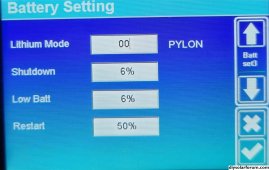
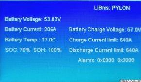
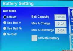
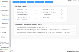
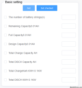
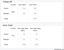
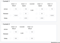
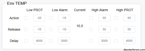
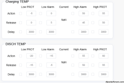
I will post a few screenshots of the BMS page, maybe these are enough for people to assist me in the search for these settings. In case someone wants to dig deeper into the program I can post a download link to the program I am using. This file is provided by my battery manufacturer.
People downloading this file can use it without having a battery connected. Of course, all the settings will be 'blank' but you can help me search for the settings deeper into the program without me having to post all the screenshots here.
I hope you guys can help me out.
I am having trouble understanding the poorly Chinese-translated BMS of my 51.2V 16S LifePo4 batteries.
Just to be sure I want to make clear that the provided manual is poor and does not include any information on the settings inside the BMS.
After a few troubles, I managed to make contact using a USB to RS485 cable to my batteries (more info here)
I am hoping someone can assist me or nudge me in the correct way for the things I want to achieve:
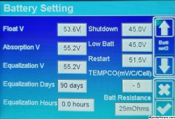
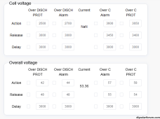
- a charging voltage of 3.45V per cell or 55.2V for the 16S pack.
- a floating Voltage of 3.35V per cell or 53.6V for the 16S pack.
- cell balancing to start at 3.4V per cell
I will post a few screenshots of the BMS page, maybe these are enough for people to assist me in the search for these settings. In case someone wants to dig deeper into the program I can post a download link to the program I am using. This file is provided by my battery manufacturer.
People downloading this file can use it without having a battery connected. Of course, all the settings will be 'blank' but you can help me search for the settings deeper into the program without me having to post all the screenshots here.
I hope you guys can help me out.
Attachments

Last edited: