


You are using an out of date browser. It may not display this or other websites correctly.
You should upgrade or use an alternative browser.
You should upgrade or use an alternative browser.
Combiner box?
- Thread starter iamrich
- Start date
Hedges
I See Electromagnetic Fields!
- Joined
- Mar 28, 2020
- Messages
- 20,660
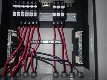
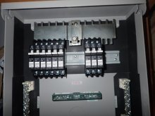
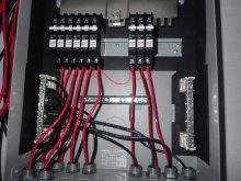
Few pictures of my midnite combiner boxes.
9 PV strings all in parallel.
With the busbars joined in the middle, there is a gap between breakers so they can't all be ganged as I suggested.
(With a hacksaw I could rearrange that pair of busbars to put breakers adjacent.)
What is Voc of the strings?
If high, that would contribute to sustaining an arc. It would also reduce the power lost with anti-backfeed diodes, if used.
I'll assume 7A or 8A Isc. Eight in parallel is 60A, more or less.
It would be interesting to see how a single backfed breaker behaves if one PV string gets shorted, takes the current from all others.
One of these days I'll buy a couple Midnight Solar polarized breakers and perform a destructive test. I've got plenty of PV strings I can set up for that.
I remeber dicussing this with you it would be interesting if you could one day test it. I would have to draw another picture to verify I understand your wiring suggestions.9 PV strings all in parallel.
With the busbars joined in the middle, there is a gap between breakers so they can't all be ganged as I suggested.
(With a hacksaw I could rearrange that pair of busbars to put breakers adjacent.)
What is Voc of the strings?
If high, that would contribute to sustaining an arc. It would also reduce the power lost with anti-backfeed diodes, if used.
I'll assume 7A or 8A Isc. Eight in parallel is 60A, more or less.
It would be interesting to see how a single backfed breaker behaves if one PV string gets shorted, takes the current from all others.
One of these days I'll buy a couple Midnight Solar polarized breakers and perform a destructive test. I've got plenty of PV strings I can set up for that.
Hedges
I See Electromagnetic Fields!
- Joined
- Mar 28, 2020
- Messages
- 20,660
We already know what the test results would be, from the story Midnight published about hooking one of the breakers up backwards.
If one of your PV strings was shorted (i.e. unplug one string of PV panels, plug MC cables from combiner box into themselves so PV+ and PV- shorted), then close the breakers, it'll open the one breaker and burn it up.
I suppose that sort of short, the reason OCP is required, hasn't happened much if at all in real life.
If you have a spare breaker you could test it too. I would keep the breaker outside the box so it doesn't scorch anything else. When you get tired of watching it burn you can shut off the other breakers feeding it; in correct direction they can interrupt full voltage and current.
Is this what your proposing so all breakers shutdown, just run a wire to combine them all?With more than two PV strings in parallel, OCP is supposed to protect a shorted string from carrying the current of two or more good strings backfeeding it.
With polarized breakers oriented to interrupt operating current in the normal direction, they are asked to trip under overload in the reverse direction. I believe they are likely to fail.
My proposal is to slip a wire through hole in handles of all the breakers, so if one trips it shuts off the others. The other breakers are carrying current in the proper direction so are able to interrupt current successfully.
With just three strings, 2x Isc is so close to allowed backfeed current I doubt it would actually cause harm to wires or interconnect.
If feeding through failed bypass diodes, those might have higher voltage drop than when in forward operation and at 2x current might overheat.
Although I think a shorted wire could handle 2x Isc, a breaker that couldn't interrupt the current would sit there carrying an arc, dissipating up to the watts of two strings in a small space. (A zero ohm short would carry full current with no power dissipation; all power would be dissipated across the PV string. An unknown impedance somewhere between zero and infinity would dissipate somewhere between zero and maximum array power.)
Besides ganging the breakers, other solutions I propose for polarized breakers are anti-backfeed diodes, or replacing them with either fuses or non-polarized breakers.
Attachments
Hedges
I See Electromagnetic Fields!
- Joined
- Mar 28, 2020
- Messages
- 20,660
Is this what your proposing so all breakers shutdown, just run a wire to combine them all?
No, not an electrical wire ganging the PV side connection together. That wouldn't cause the others to trip.
Rather, a mechanical wire (e.g. gas welding rod or other stiff wire) slid through the holes in the handles, so if one handle trips it pushes the others.
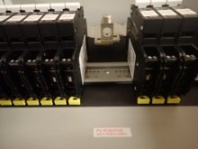
I happen to have an Outback breaker which has six, 15A 100V poles ganged together.
This would work for your group of six, but the group of 3 on the right are too far away for common trip to work.
My hack, if I tried to make that panel work, would be to swap position of busbars on top so breaker positions butt together. Might have to cut the ends to get them close enough. Then, use two lugs to connect home run wire, one lug on each busbar. I would strip insulation in two places, feed the wire through one lug to reach the second lug so both connected. (two wires under one lug, a jumper connecting the two lugs and a home run wire, seems OK to me but code doesn't allow two wires under one screw.)
chrisski
Solar Boondocker
- Joined
- Aug 14, 2020
- Messages
- 5,192
For my RV design, I wanted a way to shut the solar panels off from where I have my batteries and SCCs. For the midnite solar combiner that controlled the six panels on my roof, that is located in the same compartment. Because I have access to cut the flow of current in the compartment by flipping both breakers, I did not put an additional circuit breaker to shut the entire thing at once.think that might be the route I take as well. I will have three strings of three (3S3P) going into the box each going into a 15amp breaker and then the combined will go to the LV2424.
For the my four portable panels in parallel, that combiner box sits up to 40 feet from the compartment, so I put a circuit breaker in to stop the current without having to walk to the parallel panels.
Done over again, I would not use a polarized breaker for my external portable panels after watching a you tube video where one caught fire after being set up the wrong way. I still would use dual pole, just not polarized.With polarized breakers oriented to interrupt operating current in the normal direction, they are asked to trip under overload in the reverse direction. I believe they are likely to fail.
Slipping a wire through the handles to trip more than one at a time just does not sound like a good idea. To me it seems like this wire would hold the C/B in the closed position instead of allowing it to trip to the open position. Are they designed for this?My proposal is to slip a wire through hole in handles of all the breakers, so if one trips it shuts off the others. The other breakers are carrying current in the proper direction so are able to interrupt current successfully.
Hedges
I See Electromagnetic Fields!
- Joined
- Mar 28, 2020
- Messages
- 20,660
Slipping a wire through the handles to trip more than one at a time just does not sound like a good idea. To me it seems like this wire would hold the C/B in the closed position instead of allowing it to trip to the open position. Are they designed for this?
They seem to be.
Schneider has 2, 3, 4 pole ganged DC breakers, providing higher voltage and/or interrupting both legs of the DC connection.
Midnight has 2 and 4 pole.
I have one from Outback, six ganged 100V 15A DC breakers for 600V application. It segmented a 600V string into 6, 100V sections.
Note metal pin sticking out of handle; it ties them all together.
I'm now using it for two panels in series, plan to use for 6 in parallel.
This ganged breaker is polarized (although not labeled like the 63A Outback next to it), but alternate breakers are apparently reverse polarity? I'm not sure, but the assembly which came in enclosure was so labeled for panel connection. Alternate breakers would have to have different construction for that to be the case.

chrisski
Solar Boondocker
- Joined
- Aug 14, 2020
- Messages
- 5,192
I understand, but have never used the ganged circuit breaker.Schneider has 2, 3, 4 pole ganged DC breakers, providing higher voltage and/or interrupting both legs of the DC connection.
Midnight has 2 and 4 pole
What I think you’re saying, is if the breaker has a hole drilled in it, you can insert a piece of wire or little metal rod to make your own ganged breaker.
I don’t know if the 150 VDC 10 amp breakers I installed have holes in the handle, but next week I’ll be looking. As I look at the breaker at http://www.midnitesolar.com/product...=Breakers&productCat_ID=16&sortOrder=18&act=p this is what I bought and it appears to have the hole in the handle.
Hedges
I See Electromagnetic Fields!
- Joined
- Mar 28, 2020
- Messages
- 20,660
Yes, they can be ganged with a rod. There may be a limit as to how many before it fails to trip them, or maybe it flexes enough that an unlimited number would pass on the message.
And here's their enclosure with an external handle turning off 6 breakers by sliding a plate that gangs them:
And here's their enclosure with an external handle turning off 6 breakers by sliding a plate that gangs them:
solarstuff
New Member
Thanks for the reply.
Do you see any danger in bringing the three lines (6 wires) into the garage through Sch 80 conduit and then just using a 3 into 1 MC 4 on the neutral side, and a 15amp MC4 fuse on each string going into a 3 into 1 MC4 and then into the controller. It would use more wire, but then the fuses would be accessible on the ground instead of needing to get on the roof.
Hey Rich,Thanks for the reply.
Do you see any danger in bringing the three lines (6 wires) into the garage through Sch 80 conduit and then just using a 3 into 1 MC 4 on the neutral side, and a 15amp MC4 fuse on each string going into a 3 into 1 MC4 and then into the controller. It would use more wire, but then the fuses would be accessible on the ground instead of needing to get on the roof.
View attachment 31665
Can I ask: What size solar awg and what size combiner?
I have 12 of the 180w bougerv's coming and I wanted to use their 4 in 1 branch connectors to step up to 24v to match my growatt 3000w.
Would you like to tell me if I'm off?
Thx anyone & everyone for their 2c!
24P SOLAR CHARGER:
Maximum PV Array Power 2000W;
MPPT Range & Operating Voltage 30VDC ~ 115VDC;
Max PV Array Open Voltage 145VDC;
Maximum Solar Charge Current 80A;
BougeRv 180w (x12) 12v
Max. power voltage(Vmp): 18V
Max. power current(Imp): 10A
Open circuit voltage(Voc): 21.6V
Short circuit current(Isc): 11A
Series fuse rating: 15A
Max. system voltage: 1000V DC
J-Box IP Rating: IP65
size AWG did you use on thesolar here, and what AWG did you combine it up wire
iamrich
Solar Addict
Can I ask: What size solar awg and what size combiner?
I have 12 of the 180w bougerv's coming and I wanted to use their 4 in 1 branch connectors to step up to 24v to match my growatt 3000w.
Would you like to tell me if I'm off?
Thx anyone & everyone for their 2c!
24P SOLAR CHARGER:
Maximum PV Array Power 2000W;
MPPT Range & Operating Voltage 30VDC ~ 115VDC;
Max PV Array Open Voltage 145VDC;
Maximum Solar Charge Current 80A;
BougeRv 180w (x12) 12v
Max. power voltage(Vmp): 18V
Max. power current(Imp): 10A
Open circuit voltage(Voc): 21.6V
Short circuit current(Isc): 11A
Series fuse rating: 15A
Max. system voltage: 1000V DC
J-Box IP Rating: IP65
I ended up using 12 awg wire from the roof to the combiner box (~25 feet each string). Each string is ~100v and ~8.5a and connected to a 15amp breaker. The combined output is ~100v at ~25a and that goes from the combiner to the MPP Solar LV2424 via 6awg wire (about 2 feet). No issues over the last six months.
I think given your specs above I would also run 4S3P as you mentioned. If you series 4 panels together you would need a total of six wires from the panels to the combiner box which is what I have as well. That would give you strings at ~72v and 10a, and combined ~72v at ~30a. You will be slightly over-paneled, but you would have to have a laboratory/perfect type day to get anywhere close to max.
Hedges
I See Electromagnetic Fields!
- Joined
- Mar 28, 2020
- Messages
- 20,660
You will be slightly over-paneled, but you would have to have a laboratory/perfect type day to get anywhere close to max.
"An ugly wood 'solar pantry' and pallet stands for panels
") "
"By the profile and photo, panels are on portable ground mounts (if you ever get high winds, drive some stakes into the ground to anchor them.)
If you orient some series strings towards morning sun and some towards afternoon, that extends hours of production and reduces peak. At a 90 degree angle (6 hours difference), area presented to sun is just 0.7 times as much as a single orientation, so you could put in 40% more panels without having production clipped due to overpaneling.
solarstuff
New Member
Thanks so much, learning as I go!I ended up using 12 awg wire from the roof to the combiner box (~25 feet each string). Each string is ~100v and ~8.5a and connected to a 15amp breaker. The combined output is ~100v at ~25a and that goes from the combiner to the MPP Solar LV2424 via 6awg wire (about 2 feet). No issues over the last six months.
I think given your specs above I would also run 4S3P as you mentioned. If you series 4 panels together you would need a total of six wires from the panels to the combiner box which is what I have as well. That would give you strings at ~72v and 10a, and combined ~72v at ~30a. You will be slightly over-paneled, but you would have to have a laboratory/perfect type day to get anywhere close to max.
solarstuff
New Member
Thanks for the idea...I like the mixed angle idea."An ugly wood 'solar pantry' and pallet stands for panels
By the profile and photo, panels are on portable ground mounts (if you ever get high winds, drive some stakes into the ground to anchor them.)
If you orient some series strings towards morning sun and some towards afternoon, that extends hours of production and reduces peak. At a 90 degree angle (6 hours difference), area presented to sun is just 0.7 times as much as a single orientation, so you could put in 40% more panels without having production clipped due to overpaneling.
And yeah, it's ugly but it works....
solarstuff
New Member
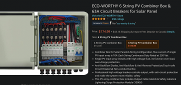
I'm looking at this combiner box from Eco-Worthy (not an affiliate link!): whould you trust it?
- Input Circuits/Circuit Breakers: 6
- Circuit Breaker Rating: 10A
- Max Total DC Output Current: 60A
- Max Input Voltage Rating: 250V
- Max Output Voltage Rating: 250V
- Max. power current(Imp): 10A
- Open circuit voltage(Voc): 21.6V
- Short circuit current(Isc): 11A
- Series fuse rating: 15A
- Max. system voltage: 1000V DC
Amazon.com : ECO-WORTHY 6 String PV Combiner Box & 63A Circuit Breakers for Solar Panel : Garden & Outdoor
Amazon.com : ECO-WORTHY 6 String PV Combiner Box & 63A Circuit Breakers for Solar Panel : Garden & Outdoor
www.amazon.com
Attachments
Last edited:
iamrich
Solar Addict
Only thing I don't like is "Max current of single PV input array is 10A" You will be right at the limit, possible over.I'm looking at this combiner box from Eco-Worthy (not an affiliate link!): whould you trust it?
My Panels (x 4S3P):
- Input Circuits/Circuit Breakers: 6
- Circuit Breaker Rating: 10A
- Max Total DC Output Current: 60A
- Max Input Voltage Rating: 250V
- Max Output Voltage Rating: 250V
SO...does this eco-worthy combiner pass the sniff test?
- Max. power current(Imp): 10A
- Open circuit voltage(Voc): 21.6V
- Short circuit current(Isc): 11A
- Series fuse rating: 15A
- Max. system voltage: 1000V DC
Amazon.com : ECO-WORTHY 6 String PV Combiner Box & 63A Circuit Breakers for Solar Panel : Garden & Outdoor
Amazon.com : ECO-WORTHY 6 String PV Combiner Box & 63A Circuit Breakers for Solar Panel : Garden & Outdoorwww.amazon.com
solarstuff
New Member
Doesn't matter: not certified in Canada so it's off the list. Thanks Rich!Only thing I don't like is "Max current of single PV input array is 10A" You will be right at the limit, possible over.
chrisski
Solar Boondocker
- Joined
- Aug 14, 2020
- Messages
- 5,192
I almost ordered that and went with a mod it’s MNPV-6I'm looking at this combiner box from Eco-Worthy (not an affiliate link!): whould you trust it?
I don’t know if this is certified for Canada, but I would not doubt it is.
I did not like the Ecoworthy for a couple of reasons. Mostly because it was pre-built for additional stuff they sold, which was not what I was using.
The first was the MC4 connectors on the outside. THat’s just an extra failure point. Instead, for the Midnite, the same hole is there except I install a cable gland in the hole I run wire all the way from the roof through the cable gland which gets connected directly to the circuit breaker.
For the midnite, I bought the exact circuit breakers I wanted, which as you and and take off panels can change. The Ecoworthy I was stuck to the C/B that came with it. If you don’t use a series of 100 watt 18 volt panels, more than likely you won’t require 10 amps.
Also, with the Midnite, I wired it the way I wanted. I ended up putting the panels 3S2P, but I plan on growing that to at least 3S3P. My original plan I bought it for was 6P.
I think the last part was the Midnite 150 VDC circuit breakers I installed were rated for constant shut off. When I store my RV between trips, the circuit breakers are rated to turn on and off as many times as needed. I’m not sure the Ecoworthy was rated for that. I may literally trip these circuit breakers 50 times per year for storage and maintanence, and for getting some power while wiring on projects while stored.
Similar threads
- Replies
- 15
- Views
- 287
- Replies
- 7
- Views
- 847
- Replies
- 3
- Views
- 258