diy solar

diy solar

Connecting cells - ampacity

buckeyestargazer

New Member
Joined
Mar 15, 2023
Messages
37
Location
Valparaiso, IN
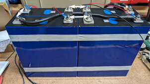
I am building a 4S 12v 230AH LiFePO4 battery and I'm thinking about putting it in a plastic case. The cells come with metal plates to tie the cells together, but the cells need to be back to back to back to back to use those.

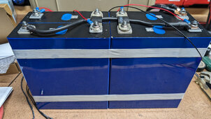
In order to fit the cells in the case I'm considering, the cells will need to be 2x end to end, and then each of those pairs back to back. I hope that makes sense.

The issue there is that I cannot use a metal plate to tie cells 2 and 3 together. To do this I'll need to instead use a wire. My question is, what gauge wire should I use for this?

Or if this is a bad idea I'll just ditch the case and tie the cells together as usual.
PXL_20240427_195744777.jpg
 
The issue there is that I cannot use a metal plate to tie cells 2 and 3 together. To do this I'll need to instead use a wire. My question is, what gauge wire should I use for this?
I would base the wire off the amps you plan to run through the battery. This is usually limited by the load, size inverter or BMS max output.

1714248916243.png
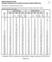
You could match the ampacity of the wire to the ampacity of the bysbars, but I do not know dimensiosn or type of materieal.
 
I would base the wire off the amps you plan to run through the battery. This is usually limited by the load, size inverter or BMS max output.

View attachment 211860
You could match the ampacity of the wire to the ampacity of the bysbars, but I do not know dimensiosn or type of materieal.

I have no idea what the ampacity of the bus bars are. They came with the cells and there is no indication on them.
I have some 1/0 welding cable that should be good up to 200A for short distances. That's what my BMS is, and I don't think I'll ever go over 150A current.
 
Or if this is a bad idea I'll just ditch the case and tie the cells together as usual.
There is another configuration where you can use just bus bars but the positive and negative will be at the cell on the top left. Bus bar one would go from that cell to the negative of bottom left cell which would be rotated 180 degrees. Then the positive of bottom left would connect via bus bar to negative of bottom right and positive of bottom right would go up to negative of top right. Positive of top right would go to negative of first cell top left.
The second issue is that tape will not provide the required compression on the center of the cells where they expand. You need metal or plywood plates to do that and that would require longer bus bars because you probably want compression in the middle as well and that means at least 1/4 to 1/2 inch to accomodate bolts or threaded rod. You may find in simpler just to stack the cells in four rows so you can use the provided plates.
 
The second issue is that tape will not provide the required compression on the center of the cells where they expand. You need metal or plywood plates to do that and that would require longer bus bars because you probably want compression in the middle as well and that means at least 1/4 to 1/2 inch to accomodate bolts or threaded rod. You may find in simpler just to stack the cells in four rows so you can use the provided plates.
The tape is temporary. Part of the reason for wanting to use the hard plastic case is to use some thinner 1/4 plywood for compression inside the case.

I'm not quite following your bus bar arrangement. Could I do this (white arrows represent bus bars)? This would put the main negative and positive terminal on the right. I just want to make sure I don't blow something up!
PXL_20240427_195744777_2.jpg
 
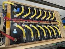
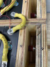
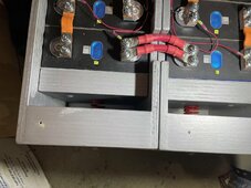
The problem with that setup is not having the same resistance with all busses. A little less or more resistance than the original doesn’t matter, but all interconnections must be the same if you even have modest amounts of charge or discharge current. What will happen is the cells will get out of balance on one side or the other of the low resistance conductor depending on charge or discharge and current. It can make balancing a nightmare. If possible, can you slot the busses? That amount of difference in length won’t matter. Just FYI, those busses are equal to a 2/0 cable for the same length, it doesn’t mean you can replace the black jumper with a 2/0, it would have to be something much more. You can however make jumpers, providing they are the same length. Do pre bend the desired bend as you cinch down the crimp as to not damage the strands if you try to bend it later. I made the batteries with the yellow jumpers during Covid and couldn’t get flexible busses so this what I came up with. Later with a different build I used flexible busses and a jump across using two 2AWG cables which for there length was exactly the same resistance as a buss. When you make your final assembly, be sure to use insulators between the cells or any metal that it can short to like a metal plate under it.
IMG_0487.jpegIMG_0673.jpegIMG_1232.jpeg
 
I have no idea what the ampacity of the bus bars are. They came with the cells and there is no indication on them.
I have some 1/0 welding cable that should be good up to 200A for short distances. That's what my BMS is, and I don't think I'll ever go over 150A current.
I have a similar problem with my busbars. I think they are aluminum, but not sure. I could contact the vendor, but other than that I don’t know.

I also found crimping short cables with thick wire challenging. The lugs were so big, the wire had almost no length and was not flexible. My short wires were not as professional as @Skypower

I opted to make my own 3/4” x 1/4” copper busbars out of aluminum and electroplated with nickel. I taught myself this at about $1 to $2 per inch for materials.
 
I'm not quite following your bus bar arrangement. Could I do this (white arrows represent bus bars)? This would put the main negative and positive terminal on the right. I just want to make sure I don't blow something up!
Yes that would also work. The easiest way for me to check it out is to draw a quick sketch. I don't have skills to upload a nice diagram. As far as compresion is concerned, 1/4 inch plywood wont stay flat in the middle and you won't get much pressure unless you find a way to bolt it in the middle. Give it a try, when the cells compress you can always adjust. In that configuration a little swelling won't put much pressure on the bus bars.
 
The problem with that setup is not having the same resistance with all busses. A little less or more resistance than the original doesn’t matter, but all interconnections must be the same if you even have modest amounts of charge or discharge current. What will happen is the cells will get out of balance on one side or the other of the low resistance conductor depending on charge or discharge and current. It can make balancing a nightmare. If possible, can you slot the busses? That amount of difference in length won’t matter. Just FYI, those busses are equal to a 2/0 cable for the same length, it doesn’t mean you can replace the black jumper with a 2/0, it would have to be something much more. You can however make jumpers, providing they are the same length.

Thanks for the info. What do you mean by "can you slot the busses"?

If I arrange the cells like in the second pic I posted (post #5) all the busbars would be the same length, so I take it that means the resistance would be the same as well.
 
Thanks for the info. What do you mean by "can you slot the busses"?

If I arrange the cells like in the second pic I posted (post #5) all the busbars would be the same length, so I take it that means the resistance would be the same as well.
Yes, if you can do that. I thought the distance of the holes wouldn’t allow that.
 
Yes, if you can do that. I thought the distance of the holes wouldn’t allow that.
The bus bars are already slotted, but I am also getting some more robust bus bars for this purpose.
Interestingly, I have the BMS connected which shows the resistance on each battery lead. And even with the long jumper as in the first image I posted the resistance is basically identical across all leads. I was expecting the resistance for the jumper to be different. Or perhaps it's only under load that the resistance would be different?
 
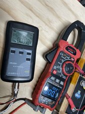
If you only charge 5 or 10 amps it would probably be ok but you’d definitely see an issue with a higher load on that jumper. An internal resistance meter can measure the difference before it’s put in operation. Another way is to use a good multi meter(resolution .xxxx) can measure a voltage drop easily with a constant load of say, 50 amps then compare across the jumper at the terminals. You take an average of what you’re pretty sure what’s good to figure out something that’s in question. If it’s not the same or close you’ll have future issues with balance.
IMG_0648.jpeg
 
Back
Top