diy solar

diy solar

Rick's recommended compression containment for EVE cells (LF280K, LF304)

rickst29

Solar Enthusiast
Joined
Mar 27, 2021
Messages
710
Location
Reno, NV
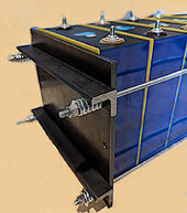
I recently purchased a set of EVE LF280K battery cells. I have built similar spring-loaded compression clamps in the past, but the 1/4" steel plate which I used in those boxes would tend to bend around the cells if I used the same "just the plates" approach this time. I also increased the number of clamping rods from four (one per corner) to six (3 per side), so that I could add three cross braces against each plate. Use of 6 springs also allowed me to by smaller springs, with max load only 141 lbs each.

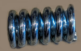
In the LF280K V3 EVE Specification and Testing document, EVE requires battery packs to provide clamping forces between 3000N and 7000N. 3000 Newtons is a bit less than 700 lbs. My travel trailer has very limited room for battery packs, so I chose this spring - it's less than 0.9" tall @ 120 lbs, with solid height .762 @ about 140 lbs. https://www.compressionspring.com/catalog/product/view/s/pc127-625-6000-mw-1060-cg-n-in
It is an expensive one, people with more room can find cheaper alternatives.

The plate height of 8.0" is exactly right for these cells. My purchased width of 9.0" was maybe a bit too much. The rod holes are good with less than 1/4" to the side edge of the plate, so that left a lot room along the sides of cells. (That extra distance tends to increase bending forces within the plates, but I addressed that with these crossbars.)

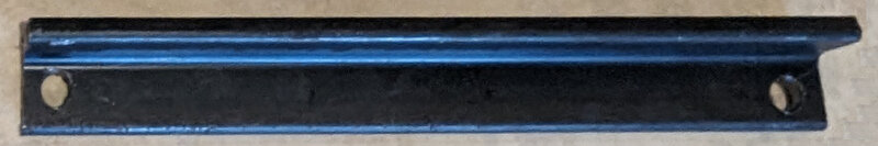
In this containment, I added three horizontal segments of 90-degree angle bar to the outside of each plate. Each segments are slightly longer than 9.0", with a bit more "beef" outside of the holes for threaded rod pass-thru. The compression springs and nuts are all outside the vertical faces of the angle bar segments, pushing against 1/2" steel (plate plus L-bar) at each hole.

Any attempt at "upward bending" from the middle of the plate pushes against the entire 1" height of the other (non-adacent) angle bar side. An attempt to bend that bar sideways (in the long direction) causes compression along one edge, with tension on the other - and they're held tight by 1/4" steel all the way through.

Unlike my earlier "copmpression boxes" (withouth these cross-bars), the new containment shows zero visible bending after tightening all the nuts. It costs a lot, but in comparison to replacement cells - it's a smart idea.

Photo shows an end plate with 2 cross-bars, 4 rods and 4 springs - the middle row not yet inserted, so you x=can see the holes. Photo #2 is the spring I used. Photo #3 shows one of the angle bar segments, with holes alreasdy drilled to match the corresponding plate. Total for the steel parts swere about $60, and total for the springs was about $50. I spent a LOT of time cutting those holes, but I have only a hand drill - not a drill press, which could run at lower spped and higher pressure. Drill bits added another $15, but i only needed to use 3 of the bits.
 

Attachments

  • compression-assembly-spring-side-with-2-rods-not-yet-done.jpg
    compression-assembly-spring-side-with-2-rods-not-yet-done.jpg
    186 KB · Views: 85
  • high-rate-compression-spring.jpg
    high-rate-compression-spring.jpg
    84.4 KB · Views: 80
  • angle-bar-stabilizers.jpg
    angle-bar-stabilizers.jpg
    46 KB · Views: 80
Use flexible or stretchable bus bars. With this clamping configuration cells will move apart as they swell which will put stress on the terminals if solid bus bars are used.
 
Yes, the two plates are cold rolled 1/4" steel plate, type "A36". The eBay seller cuts them clean, at low cost.https://www.ebay.com/itm/322748353721

There is a gigantic thread (384 posts long!) concerning the use of springs to optimize to 'optimize' the compression which is applied in a battery pack, here: https://diysolarforum.com/threads/pack-cell-compression-optimized-by-using-springs.14751/

Prismatic LFP cells The cells swell and shrink, slightly, according to both temperature and state of charge, Many posts in that Thread attempt to argue that a box with strong fixed end sides can work, in spite of the swelling and shrinking cells.

But if the end sides (applying compression) really are fixed, they behave the same as my structure with super strong "infinite rate per inch" springs installed. Just a little bit of swelling along the row of cells (through the "thickness" of each cell) would cause extreme pressure. This would be somewhat alleviated, however, by cells expanding vertically and horizontally.

The smaller surfaces of the top, bottom and narrow sides are held tight at the 90-degree joints of the cell case, and too much compression applied on the "big" faces might blow out the smaller faces or edge joints. EVE's maximum pressure (7000 Newtons allowed on a continuous basis, 10,000 Netwons instananeous) probably allows that expansion to be "OK" in a fixed box with just a few cells. But I SWAG that 16 prismatic cells in a row might approach bursting pressures, if held in fixed position on those compression sides.

The use of springs allows the spring loaded plate to give the cells some expansion room: The outside springs become more compressed, pushing the plate with extra pressure according to the spring "rate". The "rate" on the springs I used is about 750 lbs per inch, with only 0.187" of distance between "free length" (1.06") and "compressed height" (0.762"). I tighten the springs to about 120 lbs by using 85% of that free length, leaving only 15% (0.159") of remaining free height) to handle cell compression, before the spring become fully compressed. The total pressure from the plate is about 845 lbs when they have been pushed to that limit - it will goes non-linear (like a fixed box) after the springs are fully compressed.

My margin for additional expansion distance is fairly small, but other members have reported only tiny changes in the total width of the cells within compressed battey packs, when charging from low SOC to very high voltage (3.65 per cell, a value which I will never reach with mine). A row of even 16 cells should see less than 1/8" of movement, so my 4S pack should be fine. I can even turn it into a double pack (8 cells compressed together, run as 2 packs of 4S using 2 BMS units) with no issues.

Some people have talked about using foam instead of springs, but I feel that foam doesn't compress in a linear way, and it "wears out" over time - failng to maintain high pressure, and spring all the bqck when cells shrink.
 
Use flexible or stretchable bus bars. With this clamping configuration cells will move apart as they swell which will put stress on the terminals if solid bus bars are used.
YES! I strongly agree with this build strategy. Fixed length bus bars will stress the underlying terminals by holding the distance between alternating but adjacent cells "fixed" at the top, twisting the whole pack (free to strech a bit, lower down) in really bad ways. The cells will be damaged, and the bus bars will tend to work lose from their terminal bolts.
 
I just strap the cells (which are individually wrapped in Kaptom tape) with three rows of strapping tape (moderately applied) and build a fairly tight box lined with 1/4 rubber flooring and shim the cells with that thin plastic cutting board material until they are tight. Allows for a small amount of movement with a resistive force.

Easiest, simplest method that uses the least room and no digging into newtons or over engineering.

IMG_5762.jpeg
 
Interesting to see across the forum everything from spring-loaded restraint to a bunch of cells just sitting on a shelf.
I wonder what we will learn after 5, 10, 15 years of service, ie if we start to see any differences after long term cycling. Time will tell.
Any automotive packs I have seen pics of open, don't seem to have any spring-loaded restraints, unless the goop they use serves this role. They do have metal enclosures and flexible bus-bars though it seems.

on a side note, considering the pressures discussed, we can be sure that some of those packs that stack cells on their sides, vertical one on top of another are clearly not 'over stressing' the bottom ones, since the stack of cells sure isn't 700lbs. Laying cells on their sides sure looks like a bad idea to me, I keep mine all upright.
 
I just strap the cells (which are individually wrapped in Kaptom tape) with three rows of strapping tape (moderately applied) and build a fairly tight box lined with 1/4 rubber flooring and shim the cells with that thin plastic cutting board material until they are tight. Allows for a small amount of movement with a resistive force.

Easiest, simplest method that uses the least room and no digging into newtons or over engineering.

View attachment 194365
Cheap and easy (and I love the presence of a class-T fuse). But totally inadequate per EVE REQUIREMENTS.

(The requirements, for better or worse, do specify 3000 Newtons of clamping force.)
 
Cheap and easy (and I love the presence of a class-T fuse). But totally inadequate per EVE REQUIREMENTS.

(The requirements, for better or worse, do specify 3000 Newtons of clamping force.)
Good thing they are CALB cells.

Strapped, tightly in a box with a bit of firm rubber allowing for slight movement with some level of resistance. Good enough.

“Perfection is the enemy of progress.” Especially when you have other builds going with complex systems.
 
Interesting to see across the forum everything from spring-loaded restraint to a bunch of cells just sitting on a shelf.
I wonder what we will learn after 5, 10, 15 years of service, ie if we start to see any differences after long term cycling. Time will tell.
Any automotive packs I have seen pics of open, don't seem to have any spring-loaded restraints, unless the goop they use serves this role. They do have metal enclosures and flexible bus-bars though it seems.

on a side note, considering the pressures discussed, we can be sure that some of those packs that stack cells on their sides, vertical one on top of another are clearly not 'over stressing' the bottom ones, since the stack of cells sure isn't 700lbs. Laying cells on their sides sure looks like a bad idea to me, I keep mine all upright.
The weight total of cells stacked into vertical rows, at only 5.6kg each, would create only a trivial addition in pressure on the bottom-most cell, in comparison to both the the minimum clamp requirement (about 306 KgF at sea level) and the maximum allowed (about 714KgF).

Perhaps the assembly in those automtive packs is really tight to begin with, or they completely ignore EVEs requirement. EVE also says that the cells must be oriented with terminals on top, although I am not sure why they state that requirement. Perhaps the LFP gel versus anode rod surface interface develops issues more rapidly, wihen micro-bubbles float towards a different surface under gravity. That's SWAG, I really have no idea.
 
minimum clamp requirement (about 306 KgF at sea level) and the maximum allowed (about 714KgF)
Does EVE also require lateral minimum clamping pressure - to contain the short sides as the long side is loaded?
We can expect the thin aluminum cases to offer very little restraint on their own, 300 - 700 kg of force on the case sides should lead to the battery bulging out across the unsupported ends, unless also restrained. Curious if they address this condition.
i like the way you think.
 
Are cylindrical cells a better over all design then, since the circular container can more effectively restrain the contents without requiring the preload that the prismatics stipulate?
If I recall I read a study where cylindrical cells were overcompressing the cell roll over time due to inability of cylinder to expand as cell material swells. And cylinders are not space efficient when making a pack.
 
Some people have talked about using foam instead of springs, but I feel that foam doesn't compress in a linear way, and it "wears out" over time - failng to maintain high pressure, and spring all the bqck when cells shrink.
We shall see who prevails in this argument down the road in the future.

I'm very confident in my approach. :cool:
 
Yeah, I am expecting I will be upgrading to some fantastic new battery chemistry in about ten years, long before my current cells actually drop off in capacity. I don't compress, but I still follow along those that do.
 
Without wanting to side-track this spring tension thread, most people have only ever discussed recommended compression from the EVE data sheets, but EVE are a small manufacturer.

Looking at some others, I can only see the mention of 300Kgf for the Envision 305Ah cells, but only in relation to the dimensions section in the sheet for the cells, there's nothing about compression during service.

I have 3 data sheets for the Gotion 340Ah cells.

The earlier versions (2021) had two different sets of compression one for the dimensions drawings:

5% SOC 200Kgf

2021 version.jpg
Then for compression: Max 300Kgf @ 5% SOC
Min 50Kgf @ 5% SOC

2021.jpg

The latest version from 2022 though still has two different compression settings, but now it's 17+-3% SOC with 200+-20Kgf for the Dimensions:

Screenshot 2024-02-09 005003.jpg

Screenshot 2024-02-09 005448.jpg

Also the pack compression advice has updated:

Max Compression (During pack assembly) of 600Kgf 17%+-3% SOC
Min Compression (Optimal after pack assembly) of 150+-50Kgf 17%+-3% SOC

Screenshot 2024-02-09 005124.jpg

They also show method of compression:

Screenshot 2024-02-09 005215.jpg

Take from that what you will, but I do wonder if keeping a constant compression with springs is really what the cells need or want, when I've also never seen any mass produced pack with springs? The Gotion cells all have a very uniform identical concave belly on them, I'd guess this is to allow the 11% or so expansion variation through the charge cycle to expand into, whilst being in a fixed enclosure at 150Kgf. Springs could allow cells to 'walk around' in an enclosure and maybe even rub or wear, maybe not a problem, and I tried reading the 300+ pages of the spring thread and gave up :LOL: For me, simpler to stick to fixed like the large manufacturers do.
 
Last edited:
Back
Top