diy solar

diy solar

New DIY battery. Feedback on design needed.

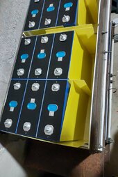
Here is the second "shelf". I still have to order fuses and cables.

View attachment 230150

Each battery will have its own NH00 400A fuse and the whole busbar will have 630A. These sizes are decided not to protect any equipment, but to avoid having the building self destruct if one of the batteries , inverters or wiring develops a short.

Having spent half of my weekend plasma cutting these parts (by hand) in scorching sun I think ill leave my vertical battery as is for the time being (you can see a parts of it on the left).

Edit: How important is it to get cable lengts exactly right when paralleling batteries? These are all different capacities anyway (314ah, 306AH, 280AH, possibly 260AH if i build the frankenbattery).

So currents will not be equal. Lets say one battery would have a cable 2m longer than another. Realistically will this cause a large current inbalance?
Have you put a strait edge against the bottom of the steel plate to see how straight she is?

If it’s straight now I wonder how it will be after a few weeks or years.
 
Have you put a strait edge against the bottom of the steel plate to see how straight she is?

If it’s straight now I wonder how it will be after a few weeks or years.
Is minimal is that deflection could be it is only gonna change if you had a removed weight

Edit: Plus he uses extra foam at ends of cells and prebenses bus parts to compensate for sag :LOL::ROFLMAO:
 
Last edited:
Have you put a strait edge against the bottom of the steel plate to see how straight she is?
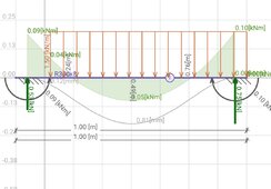
I calculated the bend amount well before I started cutting, but thanks for asking :)

Screenshot_1721604420598.jpg
I don't have a straight edge capable of showing 0.8mm over 1m distance on rusty steel.

If it’s straight now I wonder how it will be after a few weeks or years.
It'll be exactly as it is now. See screenshot above. It's well within the elastic deformation regime.

Anyone who worked with 10mm and 8mm steel plate knows how tough that stuff is. Pressure plates are 10mm, the "shelf" is 8mm, the concrete blocks are what the wall behind is built with - if they fail there is a far bigger problem as this is 2m underground 🤣

The pressure plates are under a lot more strain than the shelf. And they are narrower. But it's fine.

Is minimal is that deflection could be it is only gonna change if you had a removed weight

Edit: Plus he uses extra foam at ends of cells and prebenses bus parts to compensate for sag :LOL::ROFLMAO:
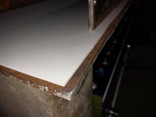
Exactly. Here you can see some construction details before the cells were put in
Compress_20240722_013430_0106.jpg
(Yes, it's not pretty, but it'll work) I will add "something" to the concrete blocks before putting the third and fourth shelves on. It'll be either a steel bar (one on each side). Or more concrete blocks with actual mortar to bond everything together.
Compress_20240722_013429_9758.jpg
The white stuff is "PVC foam". Sorry I have no idea what this stuff is called in English. When you hold it in your hand it feels as hard as wood. Not hard wood. Something between balsa and spruce. But it is a kind of foam and it compresses when under pressure. Like styrofoam, but styrofoam is made with styrene while this is made with PVC.

Of course the disadvantage of using this is lack of insulation at high temperatures.(PVC will squeeze out above 100C). That's why there is fr4 in there in case things get really hot during thermal runaway etc.
 

diy solar

diy solar
Back
Top