Short Answer: ~120 Amps if the resistivity of type M hard pipe were the same as copper. I suggest slowly ramping up the current on your system 10 amps at a time and watch the busbar temperature to confirm. Let us know what you find.
Long answer:
It would be easier to just measure it with an Ohm meter.... but...I just worked the first part of the math for wire this morning for @
ianganderton here.
It depends on the thickness of the copper pipe and the hardness (which affects resistivity). There's 4 types of "hard" copper I know of (e.g., K, L/ACR, M, and DWV).
Example math:
1/2 Pipe, type M: 120mm long, 15.8 mm outer diameter, .7 mm thick wall, resistivity 1.7e-8 Ω m (?)
If you pound the pipe flat, it would be 1.4 mm high and width = π x d/2, so 24.8 mm.
Ω = 1.7e-8 Ω m L/A
A = 1.4 x 24.8 = 34.27 mm^2 = 3.427e-5 m^2
Ω = 1.7e-8 Ω m 0.12m / 3.427e-5 m^2 = .059 mΩ
Joules Law: H = I^2 x R (ignoring T for DC)
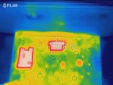
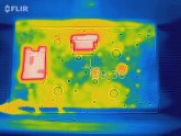
The temperature of the busbar will rise until the heat leaving equals the heat generated. How much heat leaving the busbar depends on the shape, ambient conditions, airflow, etc.
I was about to attempt to figure this out when I realized probably only @
ianganderton wanted to know that much detail and I'd spoil his fun by just spelling it out (that and I don't know ;-).
Fortunately there's a shortcut. Knowing the area is 34.27 mm^2, we can calculate the diameter as if it were wire since A = π r^2, so d = 2r = 6.6mm or ~ gauge 3 (rounded down). From this
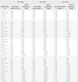
ref, the max amps for AWG 3 in air is 153 amps. I know we already rounded down once, but since it's not pure copper let's take off 20% for safety... call it 120 amps?
It'll be interesting to see what those who have a lot of experience with busbars think of this.... @
fhorst, @
Steve_S and
@Haugen (I know there are more, these are just the ones that popped into my head) -- linking you all so you can put some practice to this theory.
Thanks,
@svetz I really appreciate you doing the math! (I'm getting different results though; see below)
Firstly, I didn't know that there were different types of 1/2-inch copper pipe. I just walked into the big orange store and bought one of the precut lengths they had in the bin.
Without going back to the store, I believe (from a quick web search) that it's:
1/2 inch x 3 ft. Copper Type L Hard Temper Straight Pipe. In other words, Type "L".
I believe "L" is thicker than "M", from:
https://en.wikipedia.org/wiki/Copper_tubing#Sizes
As far as purity of copper, I believe nearly all copper pipe sold in N. America, from
ASTM B 42 - Standard Specification for Seamless Copper Pipe, Standard Sizes, would be at least 99.9% pure copper.
So hopefully we can remove the 20% safety margin.
Here's my calculation. TL;DR is that
1/2-inch Type L cable is a slightly better conductor than AWG 1.
===========
From the
Wikipedia article, Type L has an Outside diameter of 15.875mm and an Inside Diameter of 13.843.
Following in your footsteps for doing the math, the area of this OD would be:
A = π r^2 = 3.14159 * (15.875 / 2)^2 = 3.14159 * 63.0 = 197.9 sq. mm
Similarly, the area of the Inside Diameter would be 3.14159 * (13.843 / 2)^2 = 3.14159*47.9 = 150.5 sq. mm
Subtracting the area of the inside from that of the outside should give us the cross-sectional area of the copper itself.
197.9 - 150.5 =
47.4 sq mm.
Let'd double-check using a different method since I'm old and it's been decades since I've done any math:
Using good old "Length x Width". Let's take length as circumference and width as the thickness of the copper.
I'm going to calculate an Avg circumference to try to get a "better" circumference of the copper pipe for calculating the cross-sectional area. Hopefully more accurate than using just the OD or ID.
Circumference OD = 2 pi R = 2 * 3.14159 * (15.875 / 2) = 49.87mm
Circumference ID = 2 pi R = 2 * 3.14159 * (13.843 / 2) = 43.49mm
Avg circumference = (49.87 + 43.49) / 2 = 93.359/2 = 46.68mm
What is the thickness of the copper in 1/2-inch Type L copper pipe?
OD = 15.874 mm
ID = 13.843 mm
The difference between OD and ID should be 2 x thickness.
Therefore Thickness = (15.874 - 13.843) / 2 = 2.03 / 2 = 1.016mm.
Area = Thickness x circumference = 1.016 x 46.68 =
47.40 sq. mm
Yay, the 2 methods agree!
If this area (47.40 sq mm) were a circle, what would its diameter be?
D = 2 x r = 2 x sqrt(A / pi) = 2 x sqrt (47.40 / 3.14159) = 2 x sqrt(15.09) = 2 x 3.884 = 7.77mm
D = 7.77mm
That is, I propose that 1/2-inch Type L copper pipe is similar to a copper rod of diameter 7.77mm.
Using the
AWG wire chart referenced by Svetz, the closest-without-going-over wire gauge is AWG 1 at 7.348mm, with a Max current in air of 211A.
I therefore submit, with a sigh of relief--because I can use the bus bars I had already made--that
my crude banged-out-of-copper-pipe bus bar is better than an AWG 1 cable and can thus safely handle my need to conduct 200A.
Since this has been a long comment already, I'll go even further and show the "real-world" situation.
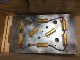
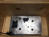
I have a spare piece of the raw hammered-out pipe. And I using a micrometer, the width of the bar is just under 24mm and the thickness is just over 2mm. The approximate cross-sectional area is thus about 24 x 2 = 48mm, pretty close to the theoretical 47.4mm. I say "approximate because it's not perfectly flat in any direction. This piece was from an early attempt. The ones I've ended up using were done with a small 3lb sledgehammer onto a kind of an anvil and those are quite flat on one side (and I use that flat side to contact the lugs of cables).


If anyone sees any problems, let me know. I don't want to start a fire. However, I doubt I'll ever get near 200A.
The biggest consumer of power in my rig is my induction burner at 1800W on max (I intentionally never run it at max). I'd have to do something silly like run a toaster and the induction burner at the same time.