diy solar

diy solar

Lugs Electrical Contact Questions

jt_retro

New Member
Joined
Jun 13, 2020
Messages
66
Hi Folks

I have some questions regarding M8 and M10 lugs and I'd be grateful for some help.

My 12V DIY solar system consists of 5 SCCs (200A total max), 2 Battery Chargers (120A total max), 2 LifePo4 batteries, a BMV-712 shunt, 2 x Victron 250A 6 post Bus Bars (+ve and -ve), and a Giandel 4000W inverter. All in parallel via the bus bars (with the exception of the batteries, which are joined in parallel directly together).

1) My equipment, annoyingly, has different sized terminal posts/holes from each other. In principal, is it safe to use an M10 lug on an M8 stud/hole (using 8mm nuts/screws), as long as the surface area around the M10 lug is in contact with the metal plate surrounding the post/hole?

2) Is it safe and accepted practice to have multiple lugs on a single post/hole?

3) As mentioned above, I use Victron 250Amp busbars. Whilst 250Amps is enough for the total current from my SCCs and battery chargers (which are never on at the same time at max current), the current from the batteries to the inverter could be as high as 500Amps. Am I still ok to use these undersized busbars as long as my inverter lugs and battery lugs are on the same post (thus, in theory, no current from the battery is going through the bus bar) ?

4) If safe, what is the best way to mount 2 eg. M10 lugs together on the same post/hole? I can never seem to get 100% coverage of the upper lug on the bottom one.

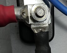
This is what I have (ignore cable colours!): IMG_0973.jpeg
5) Does anyone use a Littlefuse Mega with M10 lugs? If so, is this safe?

6) What is the tradeoff of doing 1-3 above vs just reordering cables with correct lugs as well as the Victron 600A busbars (apart from cost, of course). I'd rather not have to do this as long as 1-3 is safe, but your help would be appreciated.

Thanks folks!

Cheers

JT
 
Last edited:
In principal, is it safe to use an M10 lug on an M8 stud/hole (using 8mm nuts/screws), as long as the surface area around the M10 lug is in contact with the metal plate surrounding the post/hole?
I have done it. But literally “in principle” it is not ok on one hand and suboptimal on the other. It’s going to be held on tight enough, but on a 4000W! 12V system there’s a lot of current potential that needs to happen at the point of contact.
Is it safe and accepted practice to have multiple lugs on a single post/hole?
No. People do it; I might do it if the battery to inverter was on the bottom and a small/thin meter/sensor ring terminal was on top or maybe an SCC output was on top in a smaller system. Most often, however, the bolt length will lose a couple of threads which weakens the potential holding power of the threads. I use a busbar.
Am I still ok to use these undersized busbars as long as my inverter lugs and battery lugs are on the same post (thus, in theory, no current from the battery is going through the bus bar) ?
I have done that when my system was 200W but undersized anything is a poor idea. Just get bigger busbars? Victron is quality stuff and will probably “take it” but fires don’t care about “probably.”
What is the tradeoff of doing 1-3 above vs just reordering cables with correct lugs
just buy the tinned terminal ends of the right size and an appropriate hex crimper for your probably 4/0 or 3/0 cables. That will likely cost nearly the same as new cables.
You are looking at what? 350A+ on that inverter? There is no trade off for safety.
I might consider 3000W at 12V for myself but realistically? 2500W+ is about the ceiling of practicality and safety in a 12V system imho
 
1. If you find yourself using larger cable lug hole sizes compared to bolt it likely will not be a problem. I am sure everyone ends up having that happen at some point. Just make sure everything is good and tight and check for heat under heavy loading.
2. Multiple lugs require that you do not place anything between them such as a washer. Again keep a eye out for hot spots.
3. I have no opinion.
4. See #2
5. Never tried it.
6. Temco makes a good assortment of lugs and cables. Not a bad idea to upgrade your stuff after you figure out what you need.

I endorse everything 12VInstalls stated in his post with one exception. If your system is going to be in indoors, and not subject to a harsh environment go with plain copper and not tin coated lugs. Copper to copper will be the best conductivity.

My 2 cents.
 
Just looking at your list of components including multiple SCC's is pretty much textbook for going with a higher voltage system.
Thanks, however this isn't financially viable. This is a DIY system that has been built up over time. I will say I'm quite happy with how everything is performing. I just would like to understand lug connectivity better.
 
My off grid set up is going your route. For buss bars I'll get either all M8 and drill the 2 3/8, M10 or get a buss bar with both. Always use tinned buss bars even indoors they form corrosion over time.
 
I wouldn't bat an eye putting a M10 on a M8 post. ABYC permits stacking lugs up to 3 on one stud so I wouldn't worry about that either, permitted you put the highest current lugs the closest to the bus bars. Victron's 250A and 600A bus bars are drastically underrated and I would never bat an eye pushing way more than 250A through their 250A bars. If you compare the cross-sectional area to a chart for bus bars you will see what I mean.

Megafuses should always be used in a proper megafuse holder, which almost always are M8 for the fuses - hence why it's nearly impossible to find M10 Mega fuses.
 
however this isn't financially viable
I have bought decent multi-sizes bare-crimp ring terminals that are decent quality and thickness for like $20
These assortments have enough pieces to do 4+ cables (one pair) and cost so little compared to small bags of a coupla sizes.
WindyNation sells 2/0 etc welding cable with crimp ring terminals and heat shrink for a decent price as well.
I wouldn't bat an eye putting a M10 on a M8 post.
Not being argumentative here, but for just a few bucks you can buy the right sized ring terminal ends; he’s doing 4000W nominal and on 12V that’s ~330A+ - I’m admittedly ‘heat sensitive’ and oversize batt-inverter cables so I’m askeered of the reduction in contact area. ? Call me chicken.
permitted you put the highest current lugs the closest to the bus bars. Victron's 250A and 600A bus bars are drastically underrated and I would never bat an eye pushing way more than 250A through their 250A bars
the bus bar will accept that with plenty of threads; the three batteries I’ve experienced barely have enough bolt length in aluminum or brass for one ring terminal imho. Maybe I’m wrong or too skeered; could be.
I still think it optimal to only stack, say, the inverter feed over a battery cable that is in direct contact with the busbar though I do trust ABYC.
If your system is going to be in indoors, and not subject to a harsh environment go with plain copper and not tin coated lugs. Copper to copper will be the best conductivity.
True. Myopia of me living in Vermont makes me like the tinned terminals.
just would like to understand lug connectivity better
The more contact surface area the less the resistance. Less resistance less chances of heat build. Heat and fire is my OCD with stuff.
At 40- or 50A 12VDC nominal and higher I start getting nervous haha. So I go as far as I can to get stuff over done or perfect.
I endorse everything 12VInstalls stated in his post with one exception
And I endorse what you said?
Multiple lugs require that you do not place anything between them such as a washer
i should have said that; washer under the nut only.
 
Not being argumentative here, but for just a few bucks you can buy the right sized ring terminal ends; he’s doing 4000W nominal and on 12V that’s ~330A+ - I’m admittedly ‘heat sensitive’ and oversize batt-inverter cables so I’m askeered of the reduction in contact area. ? Call me chicken.
I don't mean to argue either. Just in my opinion, 1/32nd of an inch all the way around seems like we are literally splitting hairs here.

barely have enough bolt length in aluminum or brass for one ring terminal imho
I am referring specifically to the bus bar in this case with a stud connection that has plenty of threads. A battery that has a bolt and barely enough threads to reach the proper torque is a different circumstance entirely.
 
SolArk appears to have 5/16" (M8) studs but manual requires 3/8 terminals for battery connections.
5k-1p uses M6 bolts, 5k-2P, 8K-2P and 12k-2P uses M10 bolts, 15k uses two M8 studs. Make sure the proper manual is being referred to.
 
15k, using the printed manual that came in the box with it. I thought the 3/8 lugs were loose so I ordered some 5/16. Was reading through the manual again before connections and noticed it wanted 3/8. Thought that was even more odd than the requirement for dual battery connections to get full rated power.
 
Hi All

Thanks for all of your feedback. The thing I didn't mention initially was that I am upgrading my inverter and battery cables (to 95mm2) so I am in the position to order cables with the correct lugs.

The not financially viable comment referred to upgrading the voltage of the system.

I have decided to go for a compromise solution regarding the lug sizing: the lugs connecting to the batteries, inverter, BMV shunt and the megafuses will be the correct size. The only m10-on-m8 will be the ends of the battery and inverter cables on the busbar. This will allow me to upgrade to a higher amp M10 busbar in the future if necessary. Does this sound reasonable?

I'd be grateful for any comments on my battery+inverter cables picture - is this the "best" way to mount 2 m10s on top of each other?

On the other studs of the busbar with cables coming from the SCCs (not pictured), I have no more than 3 m8's on each stud.

Thanks!

JT
 
Last edited:
only m10-on-m8 will be the ends of the battery and inverter cables on the busbar
Because a busbar is typically a plate there is no compromise of contact area. I would be ok with that- I think two of my busbar rings from the batteries are ‘too big’ and I used them because I don’t have another application for the larger ring terminals so I was being acceptably ‘cheap’ because I reasoned it was of no consequence.
comments on my battery+inverter cables picture - is this the "best" way to mount 2 m10s on top of each other
Well the nut threads are fully engaged so that’s a non-issue. And as long as the battery ring terminal is on the bottom with no washer under it, the SCC cable terminal is essentially mounted in a way that is closest to the battery… so I’d say it’s acceptable as well. Maybe it’s because I’m on my phone I can’t see it, but if a) the nut is not a flanged nut at a minimum and b) there is enough thread depth to permit a washer I’d ideally want a washer between the nut and the terminal.
 
The primary purpose of a screw or stud is to provide compression pressure on two interfacing conductive surfaces. At a microscopic level the two interfaces of flat conductive surfaces are an irregular, rough interface.

The greater the compression, the more the irregular surfaces intertwin providing for better conductivity of the interface.

The percentage of total interface current flowing through the screw or stud is a small percentage of total interface current.

The greater the area, with sufficient compression, the lower the interface resistance. The larger the screw or stud size the greater the compression force that can be achieved. There is a practical relationship between surface interface area and pressure, i.e. sometimes more pressure on a smaller contact area yields similar net interface resistance to a larger contact area, depending on contact surface roughness and oxidized/contaminated interface surfaces. Aluminum surface grows aluminum oxide very quickly which is non-conductive.

Using a lug with a significantly larger hole than compression screw or stud reduces the primary conductive interface surface area.

Using a wide lug with a small screw or stud may not provide uniform compression across the width of lug surface interfaces. Using a strong (thick) flat washer, on top, helps distribute the compression force evenly across the interfacing surfaces. A small headed screw or nut can 'pucker' the lug in the center reducing the contact interface pressure toward the outer edges of lug, effectively reducing the electrical interface and increasing contact resistance.

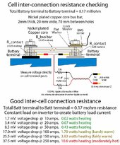
A typical 2x20x70 mm bus bar to aluminum LFP cell terminal 'good clean' compression interface has about 0.05 milliohms of resistance. The nickel-plated bus bar has about 0.07 milliohms of resistance by itself. At the bottom of the attached drawing note the amount of heating of the terminal/bus bar for various levels of current.

Bus bar connection testing.jpg
 
Last edited:
The percentage of total interface current flowing through the screw or stud is a small percentage of total interface current
the nut threads are fully engaged so that’s a non-issue
Very good explanation above. And you reminded me that i should have stated that the full thread engagement comment was referencing maximum designed clamping force on the assembly.
 
Last thing you want is screws with shallow thread penetration into cell aluminum terminals making it more likely to strip the battery terminal aluminum threads out.

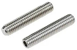
Throw away any included screws and get stainless 'grub' screws with Allen wrench counter lock ends you can bottom out in cell terminals then back out one turn to ensure maximum thread depth penetration into the aluminum cell terminal threads.
Grub screws.jpg
 
I have also used a similar setup to measure voltage drop from the battery bus bars in my EG4 6 rack to the inverter input. Positive bus bar to inverter positive with a 200 amp breaker inline, at 175 amps I read 0.3 volt drop, not to bad. On the negative side 0.02 volts.

It is also nice to know that the EG4 rack bus bars are tin plated copper with captured nuts on the backside for good thread engagement, including bolts long enough to handle the thickness of the cable terminal.
 
Thanks for all the detailed replies, but I may have caused a confusion..

The single "m10-on-m8" occurrence is only the lug (m10) on the cable coming *from* the battery on the m8 busbar stud (this is the lower lug in the picture). The upper lug (also m10) is the cable coming *from* the inverter. I guess in total this is actually a "m10 (lug)-on-m10(lug)-on-m8(busbar stud)" configuration. SCC cables are not pictured.

The connections on the actual batteries and inverter themselves will be correct (m8 lug on m8 battery terminal, m10 lug on m10 inverter terminal). Furthermore, my batteries are 2 x LifePo4 batteries in parallel. I have no access to the series strings inside each battery.

The feedback I was looking for was if my m10 (lug)-on-m10(lug)-on-m8(busbar stud) looks sufficiently good (namely, the angles of the 2 m10s to each other is of question).

Well the nut threads are fully engaged so that’s a non-issue. And as long as the battery ring terminal is on the bottom with no washer under it, the SCC cable terminal is essentially mounted in a way that is closest to the battery… so I’d say it’s acceptable as well. Maybe it’s because I’m on my phone I can’t see it, but if a) the nut is not a flanged nut at a minimum and b) there is enough thread depth to permit a washer I’d ideally want a washer between the nut and the terminal.
No flanged nuts are being used. I'm using the standard design that victron recommends in their docs: nut->washer->nut->lug (or in my case, 2xm10 lugs). You can see this here: https://www.victronenergy.com/upload/documents/Datasheet-Busbar-250-A-4P-and-6P-with-cover-EN.pdf

I'm not sure of the logic of this design, I just followed the docs.

Thanks

JT
 
Last edited:
Back
Top