diy solar

diy solar

Fusing, isolating batteries and CAN questions

totalconfusion

New Member
Joined
Dec 24, 2020
Messages
62
Hello, I have some questions about a build I’m working on. It’s mostly Victron equipment and I wanted to make sure everything is communicating the way it should be, I also have some questions regarding isolators, fuses and cable sizing.

Victron SmartSolar MPPT 250/100
Victron MultiPlus-II 48/5000/70-50
Victron Smart BatteryProtect 48V-100A
Victron Lynx Distributor (Power distribution board)
Victron BMV-712 Smart Shunt (500A)

x2 PylonTech US5000B 48V 100AH LiFePO4 batteries
PylonTech cables = 4x 2M Power Cables (4AWG, Peak Current Capacity 120A, 100A constant)
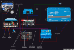


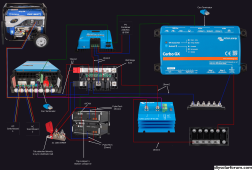
wiring diagram.png


// Batteries

1. Where do I define the max discharge limit in software? Is this part of the PylonTech BMS and can I change it using the Cerbo or do I have to interface with the BMS itself? I would like to hard limit it to 160A (0.8C on each battery)

2. The batteries have a max discharge current of 100A each but should be run at 80A or below. When run in parallel this discharge current will be 200A-160A. Is this correct?

3. I have set up DVCC. As far as I know, it’s just a way for the BMS to control the MPPT output into the batteries, is this correct? What are the advantages of using the PylonTech batteries BMS to control the MPPT as opposed to entering the charge parameters into the MPPT manually? Do they have inbuilt temperature sensors that guide the charging profile or something?

4. Is the cable configuration on the batteries correct? Should they be paralleled using the PylonTech parallel cable or is this a weak point that is under rated for the current going through it? Would I be better off ditching the short parallel cables and running both batteries independently to the Lynx distributor?

5. Should the PylonTech batteries be part of the same CAN network as the Inverter and MPPT or are the batteries better directly connected to the Cerbo by a separate VE CAN to CAN-Bus RJ45?


// Fusing and isolation

1. Should I be using x4 Class T fuses on all the battery outputs?

2. Regarding battery isolators. Are they just another point of failure and a waste of money considering the batteries themselves have a circuit breaker? If they are required, should I use them after the Class T fuses and combine the two positives and two negatives to x2 isolators, or do I need x4 isolators?

3. Post BatteryProtect I intend to have a fused 48VDC distribution board. Should I stick with MEGA fuses here like I have in the Lynx distributor? The BatteryProtect is only good for 100A so should I put a 100A fuse between the BatteryProtect and 48VDC distribution board? Or does the BatteryProtect have it’s own fuse and/or current limiting?

4. Should I fuse the MPPT battery positive and negative cables to the Lynx Distributor even though it’s a source and not a load? I guess it would protect everything else attached to the Distributor in the event the MPPT epicly fails. Should this 48VDC fuse be in the range of 120A-140A? Does the PV max current on the MPPT PV input come into play here at all for calculating the fuse value of the MPPT output? The PV input is coming in at 50A max.

I got the 120A-140A value from section 4.2 of the MPPT manual
https://www.victronenergy.com/uploa...-MPPT_solar_charger_manual-pdf-en.pdf#page=15

5. Fuse size for DC inverter input = 200A (9000 / 48 = 187.5A) - Is this calculation correct or is it undersized for peak loads?

Inverter manual: https://www.victronenergy.com/upload/documents/Datasheet-MultiPlus-II-inverter-charger-EN.pdf


// Cable sizing

1. Do the PylonTech battery cables have to take the collective loads of MPPT charging, inverter charging and battery discharge at the same time or will it be split between the four cables? If I were to turn the circuit breaker on one of the batteries off, would that overload the second battery's cables in a max current situation?

Battery max discharge = 160A-200A
Inverter max charge = 70A
MPPT max charge = 100A

Total = 330A-370A

2. Does lug positioning on the bus bar matter? Should I put the MPPT lug closest to the battery IN on the Lynx distributor?


// Communications

1. Is the Cerbo itself running VenusOS?

2. What is the ‘Battery Monitor’ setting? Should I set this as the PylonTech BMS?

3. Can I connect a VenusOS RasPi directly to the Cerbo Wi-Fi network or is it only for setup and I’ll need a real network that the Cerbo connects to?

3. What does the HDMI output of the Cerbo do? Can I hook this up to another 7” screen for a second display next to the Cerbo? Does the Cerbo accept touch input over USB?

4. Where can I confirm how the devices are communicating? I want to run everything off a daisy chained CAN. I want to confirm some devices aren’t using Bluetooth or VE.Direct for example.

5. Do I have to manually activate ‘Power control’ and ‘PowerAssist’ in software or is it enabled by default?


// Miscellaneous

1. For the 48VDC distribution side of things I’m thinking of getting one of these:


Are there any good quality 48V capable fused distribution boards that have both positive and negative bus bars integrated into the one unit other than the Victron Lynx Distributor? I had a look at BlueSea and couldn’t find one. Extra points if it has M8 studs

2. I’ve really struggled trying to get voltage ranges and charging parameters for the PylonTech batteries. The best I could get from the battery datasheet is:

Depth of discharge 95%
DischargeVoltage (VDC) 43.5~53.5
ChargeVoltage (VDC) 52.5~53.5
RecommendedCharge/Discharge Current - 80A
Max Continuous Charge/Discharge Current - 100A

How can I use this information to set some reasonable values for low voltage disconnects in both the BatteryProtect and MultiPlus-II Inverter?

What kind of DoD should I use? 90-95%?
Should I set the Inverter LVD to kick in at a slightly higher voltage than the BatteryProtect remote LVD tells it to turn off?

What bulk, absorption and float values can I use with these batteries?

3. With the BatteryProtect, should I be using mode B (relay mode)? Also how does the remote on/off for the inverter work, does it just short the wire or send a pulse?

4. Is it possible to configure AC OUT 2 on the MultiPlus II Inverter so it acts like AC 1 OUT? As in it’s always on and not contingent on there being AC incoming ie: from a generator.

5. Where can I set generator remote start parameters? I want the genset to kick in when the batteries get below 50% and keep going until they are fully charged. That way the generator won’t be stopping and starting all the time. Is this a good idea? Should I set the genset to only charge to 90% of capacity?

6. The BMV smart shunt and Cerbo have temperature sensing. Should I buy a temperature probe or would the temperature sensing do nothing on the Lynx distributor? They have weird SurLok connectors on the PylonTech batteries, not standard studs so I can’t see a way to get it on the battery terminals.


Thanks heaps :)
 
Last edited:
2. The batteries have a max discharge current of 100A each but should be run at 80A or below. When run in parallel this discharge current will be 200A-160A. Is this correct?
Correct, but not correct. The max continuous current for a 5K inverter running at 95% efficiency will be (5000W/.95)/45V = 117A. (When the battery is fully charged it will be a bit lower). Consequently, with the diagram you have you will never see more than ~ 60A from either battery due to the inverter.

The diagram shows a 48V distribution.... I am curious what that would be used for other than the Cerbo?
1. Where do I define the max discharge limit in software? Is this part of the PylonTech BMS and can I change it using the Cerbo or do I have to interface with the BMS itself? I would like to hard limit it to 160A (0.8C on each battery)
I don't think you need to limit anything. (See my previous comment)
Depth of discharge 95%
DischargeVoltage (VDC) 43.5~53.5
ChargeVoltage (VDC) 52.5~53.5
RecommendedCharge/Discharge Current - 80A
Max Continuous Charge/Discharge Current - 100A

How can I use this information to set some reasonable values for low voltage disconnects in both the BatteryProtect and MultiPlus-II Inverter?
The Pylontec batteries are 15 cell batteries. Consequently, we can't use the voltages we normally use with '48V' 16 cell LiFePO4 batteries

First, let's translate their battery voltages to Cell Voltages.
DischargeVoltage (VDC) 43.5~53.5
That is 2.9V/Cell - ??? (53.5 must be a typo)
2.9V is a tad lower than I like, but is still a reasonable low end....
ChargeVoltage (VDC) 52.5~53.5
that is 3.5V/Cell to 3.56V/cell.
3.5V is a tad higher than necessary but not out of line with what a cell can do.

Given all of this, I would set the inverter Low voltage disconnect at 3.0 x 15 = 45V and I would set the SCC Bulk charge voltage to 52.5V.
I would set the SCC Accumulate time to at least 1 hour. I would set the SCC float to around 49.5V.

However...... that is assuming you are letting the SCC make the decisions.

3. I have set up DVCC. As far as I know, it’s just a way for the BMS to control the MPPT output into the batteries, is this correct? What are the advantages of using the PylonTech batteries BMS to control the MPPT as opposed to entering the charge parameters into the MPPT manually? Do they have inbuilt temperature sensors that guide the charging profile or something?
The idea is that since the BMS knows the battery state down to the cell level, it is in the best position to control the chargers. However, different batteries do a better job than others with properly signaling what to do. Andy of the off-grid-garage channel saw one battery that never let the system go into float.... not good. Because of issues like this, You can get into holy wars with people about this. Everyone has a different opinion.
I would probably let the battery control the charging....but would check to make sure I am happy with how it is behaving. If it is acting weird, I would drop back to letting the charger decide.
4. Is the cable configuration on the batteries correct? Should they be paralleled using the PylonTech parallel cable or is this a weak point that is under rated for the current going through it?

What you show is fine as long as the cables to the Lynx can carry 75A. You could probably get away with 6AWG, but I would use 4AWG.

The alternative is to only use one 150A positive cable coming from one battery and one negative cable coming from the opposite battery. (This is called diagonal battery wiring) For 150A you need to go up to 1/0 AWG wires. These are harder to work with... but it would cut the number of fuses in half..
Would I be better off ditching the short parallel cables and running both batteries independently to the Lynx distributor?
That works too.... I am not sure there is any significant difference in any of them.

5. Should the PylonTech batteries be part of the same CAN network as the Inverter and MPPT or are the batteries better directly connected to the Cerbo by a separate VE CAN to CAN-Bus RJ45?
The network to the BMS must be separate. (Notice on the Cerbo that they have BMS-can ports separate from the VE.Can ports)

I am out of time. If I get a chance (and remember) I will come back and answer more of the questions.
 
1. Should I be using x4 Class T fuses on all the battery outputs?
You don't need 4. Put one class T on each positive coming from the battery. The size of the fuse should be 1.25 x the current expected on the wire. The wire should be sized to the trip value of the fuse.
2. Regarding battery isolators. Are they just another point of failure and a waste of money considering the batteries themselves have a circuit breaker? If they are required, should I use them after the Class T fuses and combine the two positives and two negatives to x2 isolators, or do I need x4 isolators?
You don't need isolators.
The BatteryProtect is only good for 100A so should I put a 100A fuse between the BatteryProtect and 48VDC distribution board? Or does the BatteryProtect have it’s own fuse and/or current limiting?
You should fuse the line. A 125A mega-fuse in the lynx would work well. (1.25 x max sustained current)

4. Should I fuse the MPPT battery positive and negative cables to the Lynx Distributor even though it’s a source and not a load? I guess it would protect everything else attached to the Distributor in the event the MPPT epicly fails. Should this 48VDC fuse be in the range of 120A-140A? Does the PV max current on the MPPT PV input come into play here at all for calculating the fuse value of the MPPT output? The PV input is coming in at 50A max.
Yes, there should be a fuse in the Lynx for the line to the MPPT. This fuse is there to protect from back-current from the battery if there is a short on the line. The max current from the MPPT is 100A so the fuse should be at least 100 x 1.25 = 125A. The wire should be sized to the value of the fuse.

5. Fuse size for DC inverter input = 200A (9000 / 48 = 187.5A) - Is this calculation correct or is it undersized for peak loads?
that calculation is for a 9KW inverter and a 16 cell battery. I thought you had a 5KW inverter.

The max continuous current for a 5K inverter running at 95% efficiency will be (5000W/.95)/45V = 117A. If you have two positive lines going to the battery, the current on each will be 117/2=59A. Round that up to 70 for any minor difference. The fuse should be 1.25 x 70 = 87.5. Round that up to 90 or 100 (whatever is available) The wire size should be able to cary the fuse current.

2. Does lug positioning on the bus bar matter? Should I put the MPPT lug closest to the battery IN on the Lynx distributor?
The positioning does not make a large difference. I would put the battery cables on the 'ears' coming into the Lynx. If you go with two positives and two negatives, don't stack the lugs. Put one on the bottom of the 'ear' and and the other on the top of the 'ear'. this will minimize the resistance of the connection.

3. With the BatteryProtect, should I be using mode B (relay mode)?
Yes. The settings for Mode A Li-Ion will not work for you.
4. Is it possible to configure AC OUT 2 on the MultiPlus II Inverter so it acts like AC 1 OUT? As in it’s always on and not contingent on there being AC incoming ie: from a generator.
I don't think so but the Victron gear has sooooo many options, that setting might exist somewhere.
6. The BMV smart shunt and Cerbo have temperature sensing. Should I buy a temperature probe or would the temperature sensing do nothing on the Lynx distributor? They have weird SurLok connectors on the PylonTech batteries, not standard studs so I can’t see a way to get it on the battery terminals.
The BMS in the battery will monitor the temps. You don't need the victron temp sensors.
5. Where can I set generator remote start parameters? I want the genset to kick in when the batteries get below 50% and keep going until they are fully charged. That way the generator won’t be stopping and starting all the time. Is this a good idea? Should I set the genset to only charge to 90% of capacity?
With the Vctron ecosystem, you can control the generator-start from many different locations. Your drawing shows it being hooked to the inverter so it would be a setting in the inverter.
 
Thanks for your response!

Correct, but not correct. The max continuous current for a 5K inverter running at 95% efficiency will be (5000W/.95)/45V = 117A. (When the battery is fully charged it will be a bit lower). Consequently, with the diagram you have you will never see more than ~ 60A from either battery due to the inverter.

The diagram shows a 48V distribution.... I am curious what that would be used for other than the Cerbo?
This is assuming all the load will come from the inverter, right?
Why do we use the max continuous power and not the max peak power for this calculation?
Are you suggesting the inverter is a little underrated (about 20%) to take full advantage of the batteries?

117A is over the continuous rated capacity of a single PylonTech cable. However we'll have 2 positives and 2 negatives going from the batteries to the distributor. So all good.

The 48v loads will be pretty small. Routers, media servers and IoT Home Assistant Raspberry Pi type stuff. Most of it will be switched down to 5v or 12v. I've got a tank sensor that needs 24v etc.

I like the idea of having separate LVD parameters for the BatteryProtect and the inverter. That way in the event of a let's say 90% DoD. I can cut the inverter off and reserve the remaining 5% battery to run critical loads like the Cerbo for communications and a 12v fan for a composting toilet that doesn't work if it isn't constantly ventilated.


The Pylontec batteries are 15 cell batteries. Consequently, we can't use the voltages we normally use with '48V' 16 cell LiFePO4 batteries

First, let's translate their battery voltages to Cell Voltages.
Weird! Where did you get that fun fact that from?


That is 2.9V/Cell - ??? (53.5 must be a typo)
2.9V is a tad lower than I like, but is still a reasonable low end....
Strait from the horses mouth. But typo's do happen
PylonTech US5000 Datasheet


that is 3.5V/Cell to 3.56V/cell.
3.5V is a tad higher than necessary but not out of line with what a cell can do.

Given all of this, I would set the inverter Low voltage disconnect at 3.0 x 15 = 45V and I would set the SCC Bulk charge voltage to 52.5V.
I would set the SCC Accumulate time to at least 1 hour. I would set the SCC float to around 49.5V.

However...... that is assuming you are letting the SCC make the decisions.
They seem like pretty reasonable figures. I'll probably end up letting the BMS be boss lady.
What is accumulate time?


The idea is that since the BMS knows the battery state down to the cell level, it is in the best position to control the chargers. However, different batteries do a better job than others with properly signaling what to do. Andy of the off-grid-garage channel saw one battery that never let the system go into float.... not good. Because of issues like this, You can get into holy wars with people about this. Everyone has a different opinion.
I would probably let the battery control the charging....but would check to make sure I am happy with how it is behaving. If it is acting weird, I would drop back to letting the charger decide.
Any suggestions on sussing out the BMS? I guess just looking at the graph logs in the MPPT interface would work. Any particular data points I should be looking it?


What you show is fine as long as the cables to the Lynx can carry 75A. You could probably get away with 6AWG, but I would use 4AWG.

The alternative is to only use one 150A positive cable coming from one battery and one negative cable coming from the opposite battery. (This is called diagonal battery wiring) For 150A you need to go up to 1/0 AWG wires. These are harder to work with... but it would cut the number of fuses in half..
The SurLok connectors on the PylonTech batteries are a real pain in the arse, it makes re configuring anything impossible without butchering the battery. Are there any higher rated SurLok fittings that I can fit to a bigger cable or will the receptacle have a 120A curent limit too?

The PylonTech cable ratings are: 4AWG, Peak Current Capacity 120A, 100A constant


That works too.... I am not sure there is any significant difference in any of them.
If I leave the parallel connection then won't it be underrated for the 117A from the inverter?


You don't need 4. Put one class T on each positive coming from the battery. The size of the fuse should be 1.25 x the current expected on the wire. The wire should be sized to the trip value of the fuse.
So a class T 125A fuse on each positive going to the distributor. Easy.


You don't need isolators.
Terrific. I have PV isolators which are useful. Is there anywhere else on the system you'd consider putting an isolator?


You should fuse the line. A 125A mega-fuse in the lynx would work well. (1.25 x max sustained current)
125A Mega for the BatteryProtect. What about also fusing the negative to the 48VDC distribution block?


Yes, there should be a fuse in the Lynx for the line to the MPPT. This fuse is there to protect from back-current from the battery if there is a short on the line. The max current from the MPPT is 100A so the fuse should be at least 100 x 1.25 = 125A. The wire should be sized to the value of the fuse.
125A Mega for the MPPT. What about fusing also fusing the negative?


that calculation is for a 9KW inverter and a 16 cell battery. I thought you had a 5KW inverter.

The max continuous current for a 5K inverter running at 95% efficiency will be (5000W/.95)/45V = 117A. If you have two positive lines going to the battery, the current on each will be 117/2=59A. Round that up to 70 for any minor difference. The fuse should be 1.25 x 70 = 87.5. Round that up to 90 or 100 (whatever is available) The wire size should be able to cary the fuse current.
I do have a 5K inverter. I was using peak power for the figure of 187.5A - Should I have been using continuous power?
What are the differences in calculation between a 15cell and 16cell battery? 45V vs 48V? Why do you divide by 0.95 first?
The inverter is actually 5000VA so more like 4000W right?

I'm trying to calculate the fuse size from the distributor to the inverter, you suggested that the max current would be 117A, so why are we looking at the two positive lines from the battery to the distributor?


The positioning does not make a large difference. I would put the battery cables on the 'ears' coming into the Lynx. If you go with two positives and two negatives, don't stack the lugs. Put one on the bottom of the 'ear' and and the other on the top of the 'ear'. this will minimize the resistance of the connection.
That's really good advice and for sure something I wouldn't have thought to do, thanks.


I don't think so but the Victron gear has sooooo many options, that setting might exist somewhere.
I'll suss it out on the Victron forums. If not, I'll have to combine the AC switchboards to both run off AC OUT 1. No biggie, just not as neat as I'd like.


The BMS in the battery will monitor the temps. You don't need the victron temp sensors.
Any idea if I can view these BMS battery temperature sensor values within the Cerbo/VenusOS system? I wouldn't think so. I'll ask on the Victron forums.


With the Vctron ecosystem, you can control the generator-start from many different locations. Your drawing shows it being hooked to the inverter so it would be a setting in the inverter.
That makes sense. I either haven't looked hard enough or it won't show up until I hook up the generator. I'm sure I'll find it.


Dude you're a legend. I really appreciate you taking the time and helping me understand things.
 
This is assuming all the load will come from the inverter, right?
Correct. That is a calculation for the inverter current.
Why do we use the max continuous power and not the max peak power for this calculation?
Surge currents have a short duration and therefore
don't significantly heat the wires. Consequently, we don't calculate wire and fuse size based on surge. However, Class T fuses tend to be rather fast-acting so it is always good to over-size them compared to the continuous current.
Weird! Where did you get that fun fact that from?
I had heard it before and when I saw the unusual charge/discharge voltage it reminded me. I then went out had Mr Google confirm it for me.

What is accumulate time?
There are several different names for it. I should have used the Victron ecosystem term which is Absorbtion voltage and Absorbtion duration.
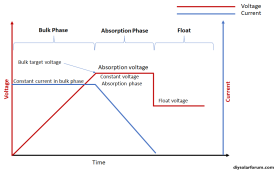
The charge controller will charge the battery till it reaches the absorption voltage. (This is sometimes called the Bulk Charge voltage.) A cheapo charger will just stop charging there.... but the batteries are not fully charged yet. They will continue to take charge for a while. A good charger will at least have a timer for how long it will hold the batteries at the target voltage till it goes into float mode. The best chargers (Like Victron) have multiple ways to configure the absorption time. The most elaborate way is to watch the current and when it drops below a certain level, switch to float mode. This versatility was really important with lead-acid batteries. With lifepo4, a timer is good enough but having the ability to tune it in is kinda fun.

Any particular data points I should be looking it?
Just watch a typical charge cycle.
What Absorption voltage does it charge to?
How long does it hold the absorption voltage after it is reached?
What float voltage is used?
Is there anywhere else on the system you'd consider putting an isolator?
None that come to mind.
125A Mega for the BatteryProtect. What about also fusing the negative to the 48VDC distribution block?
An additional fuse on the negative is not needed. Once the fuse on the positive blows.... all current stops on both legs. (It is the same answer for the MPPT and inverter as well)

I do have a 5K inverter. I was using peak power for the figure of 187.5A - Should I have been using continuous power?
I use continuous current for fuse and wire sizing. Using peak power doesn't hurt, but I feel it is overkill.
What are the differences in calculation between a 15cell and 16cell battery?

Everything is derived from the cell voltages.
I typically target ~3.45V/cell for charging and ~3.00 volts for discharge. The cells can safely go a bit higher and a bit lower, but the additional capacity gained is minimal. For a 15 cell battery, this works out to 3.45x15 = 51.75 V for charging and 45V for discharging. For a 16 cell battery it works out to 55.2 V for charging and 48V for discharge. Since the most current is drawn when the battery is low, I use the low-end voltage for calculating the current.

Why do you divide by 0.95 first?
An inverter is not 100% efficient. Some of the energy drawn from the battery gets disipated as heat and does not go out the AC ports. The Victron inverters are pretty efficient so I assumed a 95% efficiency. So, to get 5000W out of the inverter, the battery has to provide 5000/.95W

Any idea if I can view these BMS battery temperature sensor values within the Cerbo/VenusOS system? I wouldn't think so. I'll ask on the Victron forums.
That all depends on how well the Pylontec have implemented the Victron protocol. If they did it well, you should be able to see it on the Cerbo.
I'm trying to calculate the fuse size from the distributor to the inverter, you suggested that the max current would be 117A, so why are we looking at the two positive lines from the battery to the distributor?
Crap.... I had a mind fart. Sorry 'bout the confusion. It is not split to the inverter.

That makes sense. I either haven't looked hard enough or it won't show up until I hook up the generator. I'm sure I'll find it.
You might not find it in the phone app. You might have to go to the PC app.

The good news is that the Victron ecosystem is so versatile you can do almost anything
The bad news is that the Victron ecosystem is so versatile it is a PITA to find what you want.
 
This is assuming all the load will come from the inverter, right?
Correct. That is a calculation for the inverter current.
With the current setup of 2 positve and 2 negative PylonTech cables running to the distributor from the batteries, the load on each cable just from the inverter will be 75A, is that right? How much would I have left in the bank for 48VDC loads? I guess 5A if I want to keep discharge at 0.8C and 25A if I am comfortable running the batteries at 1C.

Are these calculations correct? I think I'd be inclined to stick a 25A fuse running to the BatteryProtect knowing that the system won't be running maxxed out very often and 1200 watts is more than enough for running a couple of servers.


that is 3.5V/Cell to 3.56V/cell.
3.5V is a tad higher than necessary but not out of line with what a cell can do.

Given all of this, I would set the inverter Low voltage disconnect at 3.0 x 15 = 45V and I would set the SCC Bulk charge voltage to 52.5V.
I would set the SCC Accumulate time to at least 1 hour. I would set the SCC float to around 49.5V.

However...... that is assuming you are letting the SCC make the decisions.
I will temporarily disable the DVCC and program the SCC to these values just as a precaution, then re-enable DVCC so the BMS will do it's thing. But if something goes wrong with the BMS to SCC communications, maybe it'll help. Can't hurt right?

Can you recomend an 'absorbtion/accumulation' voltage or should it be the same as 'bulk' ?

o see it on the Cerbo.


I'm trying to calculate the fuse size from the distributor to the inverter, you suggested that the max current would be 117A, so why are we looking at the two positive lines from the battery to the distributor?
Crap.... I had a mind fart. Sorry 'bout the confusion. It is not split to the inverter.
So a 150A mega fuse from the distributor to the inverter would be appropriate or oversized?


Victron & Pylontech UP2500, US2000, US3000, US2000C, US3000C, US5000, US5000B, US5000C, Pelio-L, UP5000, Phantom-S, Force-L1 & L2 [Victron Energy]
www.victronenergy.com
What a great read. A huge amount of info in there! Like this little gem. DVCC BMS control is the way to go I think.

The Pylontech battery has 15 cells in series, so 53.2V equates to 3.55V per cell. This is very highly charged and makes the system prone to go overvoltage.

It should also be noted that a LiFePO4 cell stores very little additional energy above 3.45V.

For this reason we opted to override the BMS and cap the voltage at 52.4V. This sacrifices almost none of the capacity and greatly improves the stability of the system.


I really appreciate the help and I'm now pretty confident going forward but still have a few things I'm not 100% on.


1. Are the short parallel cables being overloaded? What are they even doing in this set up? Could I just remove them entirely? Do they help balance the batteries?


2. If the four PylonTech battery cables have to take the collective loads of MPPT charging, inverter charging and battery discharge at the same time, I've calculated the load to be 330A-370A. Is this at all accurate?

Battery max discharge = 160A-200A
Inverter max charge = 70A
MPPT max charge = 100A

Total = 330A-370A

What would happen If I were to turn off the circuit breaker on one of the batteries? Would that overload the now two battery cables in a max current situation?


3. I've been looking at Class T fuses and boy are they expensive, I'm looking at $400 for two fuse holders with fuses. They all seem to have M10 (3/8) studs which is a pain because the PylonTech cables are M8 (5/16) along with most of the other gear I have. Are there any alternative fuse types you'd use from the batteries to the distributor?

Are there any Class T fuse holders that would hold two or more seperate fuses, that way I only need to get one holder and run both battery cables to it?


4. Can you weigh in on what kind of DoD I should be running to for longevity without losing a huge amount of capacity?
 
With the current setup of 2 positve and 2 negative PylonTech cables running to the distributor from the batteries, the load on each cable just from the inverter will be 75A, is that right? How much would I have left in the bank for 48VDC loads? I guess 5A if I want to keep discharge at 0.8C and 25A if I am comfortable running the batteries at 1C.

Are these calculations correct? I think I'd be inclined to stick a 25A fuse running to the BatteryProtect knowing that the system won't be running maxxed out very often and 1200 watts is more than enough for running a couple of servers.
That all seems correct.
 
Can you recomend an 'absorbtion/accumulation' voltage or should it be the same as 'bulk' ?
Yes, in Victron parlance, it is the same as bulk. Conceptually, the charge profile looks like this:

1700033286058.png
1. Are the short parallel cables being overloaded? What are they even doing in this set up? Could I just remove them entirely? Do they help balance the batteries?
They certainly aren't being overloaded. They will typically have very little current on them. You don't really need them.

2. If the four PylonTech battery cables have to take the collective loads of MPPT charging, inverter charging and battery discharge at the same time, I've calculated the load to be 330A-370A. Is this at all accurate?

Battery max discharge = 160A-200A
Inverter max charge = 70A
MPPT max charge = 100A

Total = 330A-370A

Not quite correct. The wires are either going to have charge current or discharge current, never both. To figure out the fuse and wire sizes, figure out the max total charge and then figure out the max total discharge. Use the largest of the two for charge and discharge.

In your case, the max charge is 170A and the Max discharge is ~117A + Amps to DC distribution. I'll call that 13A to make a total of 130A.
So, for calculating the wire size to the batteries we need to use the greater value of 170A. (It is a little unusual to have a charge value greater than the discharge value. ) Since there are two wires we cut that in half to get 85A. The fuse needs to be 1.25x85A=106.25A (min). Fuses don't come in 106.5A so we are probably looking at a 125A fuse.

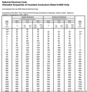
Looking at the NEC ampacity chart, that means we need at least a 2 AWG wire. 1700010385063.png

I tend to be very conservative, so I would be tempted to use 1AWG.

Note: I would be tempted to limit the total charge current to something much lower in order to keep the charge C rate down. The good news is that with the Cerbo, I believe you can leave the max MPPT charge at 100 and the max Inverter charge at 70 but impose a max total charge to something lower. If you limit it, you can also use smaller fuses and wires.

What would happen If I were to turn off the circuit breaker on one of the batteries? Would that overload the now two battery cables in a max current situation?
Yes...but maybe not. If you want to be able to run in that configuration, you will be limited to the 100A capability of a single battery. Above that the BMS of the inverter is going to shut down. So, if you want to run with a single battery, you won't be able to drive full power and your fuse needs to be 100 x 1.25 = 125A. However, because of the round-ups in the previous calculation, this is the same fuse and therefore the same wire size.

3. I've been looking at Class T fuses and boy are they expensive, I'm looking at $400 for two fuse holders with fuses. They all seem to have M10 (3/8) studs which is a pain because the PylonTech cables are M8 (5/16) along with most of the other gear I have. Are there any alternative fuse types you'd use from the batteries to the distributor?
Great question!!
First I'll give you the standard answer: You must use Class T fuses because they are the only type of fuse that has a high enough Amp Interrupt Capability (AIC).

However...... if you get rid of the parallel wires and have a fuse per battery, there is some evidence a fuse with a lower AIC such as an MRBF is sufficient.

Screeeeeeech (The sound of the gears in my brain grinding) I just realized the special cables on the Pylontec changes things.

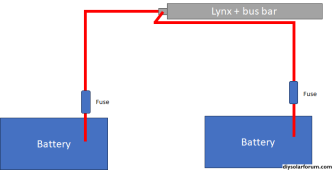
Fuses are supposed to go on the source end of a wire.... not the load end. Consequently, when adding fuses to a battery, you try to get it as close to the battery as you can. This is because if a short happens before the fuse, there is no protection.


1700033430878.png


Pylon tech clearly believes the overcurrent protection from the BMS is good enough that a fuse is not needed at the battery end.

Now the question is how this might change what you should do......

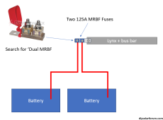
I'll start with the assumption that the fuse will not be at the battery end of the wire... with that in mind I would probably do this:

1700014225730.png

Warning: An MRBF has an AIC of 'only' 10KA. The common assumption is that 10KA is too small. However, I am not convinced it is too small for a single battery.

Are there any Class T fuse holders that would hold two or more seperate fuses, that way I only need to get one holder and run both battery cables to it?
I have seens some on line but never purchased one. Warning: There are different sized Class T fuses. Make sure you get a holder that matches the fuse you want.

4. Can you weigh in on what kind of DoD I should be running to for longevity without losing a huge amount of capacity?
I have a very different attitude on this than many other people. LiFePO4 cells have something in the order of 5000 Full charge/discharge cycles.
If you did a full discharge and charge every day it would tak 5000/365 = 13.7 years to get them down to 80% of the original capacity.

Most systems will do far less than a full charge/discharge every day. Most LiFePO4 batteries are going to die from callendar aging before they die from cycle count..... So I say drive 'em to 100% and don't worry about it. If you want to baby them.... keep the C rate low for charge and discharge and keep the ambiant temps down.
 
Last edited:
However...... if you get rid of the parallel wires and have a fuse per battery, there is some evidence a fuse with a lower AIC such as an MRBF is sufficient.
What do you mean when you say get rid of the parallel wire? just the short interconnects between the batteries or the 2 positve and 2 negative going from the battery to the distributor?

I have been looking at MRBF's as an alternative to Class T fuses. They are much cheaper and I can find good quality fuse holders with m8 studs.

Note: I would be tempted to limit the total charge current to something much lower in order to keep the charge C rate down. The good news is that with the Cerbo, I believe you can leave the max MPPT charge at 100 and the max Inverter charge at 70 but impose a max total charge to something lower. If you limit it, you can also use smaller fuses and wires.
That's good advice regarding charge C rates.


I'll start with the assumption that the fuse will not be at the battery end of the wire... with that in mind I would probably do this:
I had the same idea with the exact same Blue Sea MRBF fuse block, my only concern at the time was whether MRBF's could stand in for Class T's. I also want to keep the battery cables the same length for impedance matching, I'm not sure how much it really matters in a system like this.


I have a very different attitude on this than many other people. LiFePO4 cells have something in the order of 5000 Full charge/discharge cycles.
If you did a full discharge and charge every day it would tak 5000/365 = 13.7 years to get them down to 80% of the original capacity.

Most systems will do far less than a full charge/discharge every day. Most LiFePO4 batteries are going to die from callendar aging before they die from cycle count..... So I say drive 'em to 100% and don't worry about it. If you want to baby them.... keep the C rate low for charge and discharge and keep the ambiant temps down.
Ride it till the wheels fall off eh? I've read a lot of people running them to 90%. You're probably right about the charge C rate and ambient temperature being the real killers.

Is it the temperature, the speed at which it gets to that temperature or the cycling between hot and cold states that really screws up cells?
 
What do you mean when you say get rid of the parallel wire? just the short interconnects between the batteries or the 2 positve and 2 negative going from the battery to the distributor?
1700064930203.png
Is it the temperature, the speed at which it gets to that temperature or the cycling between hot and cold states that really screws up cells?

I have not heard of any issues with cycling. It is more about the absolute temperature. If they are sitting in a box in the sun in the desert, they are not going to last as long..... particularly if you are using them. Some (most? All?) of the problem with a high C rate is that it heats the internals of the battery. Ideally, keep the batteries in an environment between 5F and 75F. It probably can go to 90F without any significant degradation. Above 90F and you might see some degradation.
 
I'll start with the assumption that the fuse will not be at the battery end of the wire... with that in mind I would probably do this:
Any recommendations on how to mate the tab of the MRBF fuse holder to the Lynx distributor? I guess an M8 nut and bolt would do the job. What type of metal for the bolt? Would you prepare the surface first? Any special washers you might use? Also just checking the MRBF fuses are bipolar because we will be using the fuse holder 'backwards'

$50AUD each for the 48v mega fuses. Am I not looking hard enough for a good deal?
The 48v 150A megas are nowhere to be found. Would using a 200A fuse for the inverter be acceptable or most uncool?

The Cerbo power cord comes with it’s own in-line fuse. Can I just hook it up to the supply side of the 48VDC fuse block and not need another mega fuse or is that pretty bad practice?

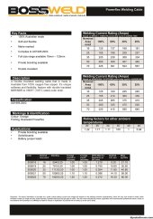
Would you be inclined to use 70mm2 fine stranded welding cable between the distributor and inverter? 35mm2 feels a bit small.
Here's the spec sheet from the manufacturer of the cable. I don't know how much I trust it.

bossweld.jpg
 
Also just checking the MRBF fuses are bipolar because we will be using the fuse holder 'backwards'

The fuse is not bipolar (but some folk think I am bipolar?)

Any recommendations on how to mate the tab of the MRBF fuse holder to the Lynx distributor? I guess an M8 nut and bolt would do the job. What type of metal for the bolt? Would you prepare the surface first? Any special washers you might use?
No special recomendations on hardware. I generally use stainless steel nuts/bolts so there is no worry of bi-metal interaction. I would definitely clean the surfaces with steel wool or a very stiff brush.

Would using a 200A fuse for the inverter be acceptable or most uncool?
200A works,
The Cerbo power cord comes with it’s own in-line fuse. Can I just hook it up to the supply side of the 48VDC fuse block and not need another mega fuse or is that pretty bad practice?
That is how I would do it.
Would you be inclined to use 70mm2 fine stranded welding cable between the distributor and inverter? 35mm2 feels a bit small.
The numbers work for 35mm.... but at least electrically, bigger is better. I don't think you need to go all the way to 70mm2, but perhaps 50?
 
Newbie question, what software did you use to make this type diagram?
Sorry for the very late reply.

diagrams.net (previously draw.io)

The high resolution images for the Victron equipment you can find on their website next to the manuals and datasheets for their products.

There are some third party libraries for Victron equipment but I've never had much success with them. Maybe one day.

Good luck with whatever you're designing
 
Back
Top