Meeko
New Member
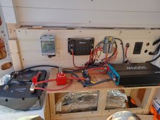
Hello, just finished our electric, (solar cables not hooked up to charge controller yet) , looking for someone to take a look. Ty


The one closest to battery terminal is 200 the other is 60 going to charge controller.Is this a couple MRBF fuses? If so, what amp rating?
The fuse from DC-DC charger should be on the source/charger end as it is to protect the wire.
View attachment 134230
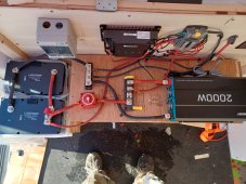
2000W inverter / 10V cutoff / .85 efficiency = 235A max drawclosest to battery terminal is 200
I would say coming from the controller which means the fuse only protects that wire if close to the charge controller.other is 60 going to charge controller.
I see the mistake on the 60 amp to the controller, it should be placed closer to the controller then to battery. I will fix that. Inverter will only be running a small water heater. 2/0 cable was used. Thank you, I'm learning.2000W inverter / 10V cutoff / .85 efficiency = 235A max draw
If you stress that inverter or get near its likely cutoff voltage you may blow the fuse. If suspect your wiring is rated for 200A so the fuse, which protects the wiring, would be the right size.
I would say coming from the controller which means the fuse only protects that wire if close to the charge controller.

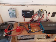
EDIT: Looks fine. I now see the MBRF fuse located on the battery.The one closest to battery terminal is 200 the other is 60 going to charge controller.

Yes, I know, just setting this up, it's been a slow build because of the weather here in Maine.(no garage) and wasn't sure about leaving then electronics out in the cold, so I've been taking them in after figuring out the placement. Good eye. TyDid you tighten all the nuts? You may want to check them all again.
For example:
View attachment 134266
Good idea, I will add.1/2 gypsum between combustable surfaces and electrical equipment mounted
Just in case things ever develop a fault and overheat is a good fire safety measure
Or alternatively a steel or aluminum sheet bonded to ground of course as a fire break would be fine
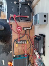
I'm not using a common positive buss bar, it's a MBRF fuse holder, and can't exceed 300 Amps, I have 280 on it now, that why it's hooked to the battery, but yes I need a breaker.OK, I see what you're saying, why not direct to the battery?
Thank you lots to go overYou have a common positive bus bar. It's right there between your switch and the inverter. You conveniently have an open stud to put the solar charge controller cable on.
Power from the solar charge controller will be used by your inverter. It's splitting hairs but when the solar charge controller is producing power, it has to go through the cable to the battery, then to the switch, then to the common bus bar, then to the inverter. If you attach the solar charge controller cable to the common bus bar you skip much of that. Loads will pull power from the bus bar, with the battery making up any difference.
To split hairs even further, and reveal how OCD I am, put the battery cable on one of the inner studs of the negative common bus bar and the inverter cable on the other inner stud of the same bus bar. Less resistance through the bus bar for power to flow from the battery to the inverter.
What you have isn't wrong. It will work, as long as you have the fuses at the right ends of the cable and the fuses are sized right.
If you need to work on the batteries, the way you have it, if the sun is out then a charge is still going to the battery even if you turn off the main switch. If you put the solar charge controller cable on the common bus bar then zero power is going to the batteries and you're free to disconnect the battery cables without any sparks.