diy solar

diy solar

Darfon Gro Watt GBLI 5001 Battery Pack- worth a punt?

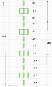
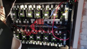
I'm pretty new to this, but from my limited knowledge for a 5p set up aren't the packs on the end of each row meant to be connected in parallel to the 3 packs in the middle ? looks like -ve terminal closest to the camera isn't hooked up to the -ve's on the 3 middle packs ? Or have I misunderstood how it's meant to work... I think as it is you've got 3 in parallel, followed by 2 in series, followed by 3 in parallel ??View attachment 112611
Yes it seems like something is wrong with that the pairs on the ends are in series therefore 7.2 v and the inner three batteries in each row are in parallel therefore 3.7 volts = imbalence
Then again I could be wrong as I have have heard that you can connect in series and parallel if done correctly you need to check the maths for total overall voltage and check what your target power capacity is and amphours and then check bms spec is ok and if it is able to balance this configuration
 
Last edited:
Yes it seems like something is wrong with that the pairs on the ends are in series therefore 7.2 v and the inner three batteries in each row are in parallel therefore 3.7 volts = imbalence
Then again I could be wrong as I have have heard that you can connect in series and parallel if done correctly you need to check the maths for total overall voltage and check what your target power capacity is and amphours and then check bms spec is ok and if it is able to balance this configuration
Yeah I think that's got to be the problem, each row of 5 is effectively 1p,3p,1p .... so if each cell is at 3.7v, each row of cells is 11.1V , there's 8 rows in series in the picture = 88.8V in total.
 
When I test the pack with multimeter I get 41v, pack isn't fully charged.
 
When I test the pack with multimeter I get 41v, pack isn't fully charged.
Maybe it's shorting through the BMS ? Or there's some other wires I can't see. Try disconnecting the BMS connectors and measure it again.
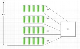
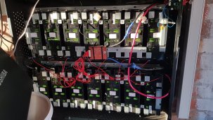
From what I can see, it's wired like the below (only drawn half the pack as it was getting rather large) 1663665407664.png
 
Last edited:
Maybe it's shorting through the BMS ? Or there's some other wires I can't see. Try disconnecting the BMS connectors and measure it again.
From what I can see, it's wired like the below (only drawn half the pack as it was getting rather large) View attachment 112678
When I test the pack with multimeter I get 41v, pack isn't fully charged.
Ah, can't see the wiring at the back.... maybe you've got 2 entire batteries in parallel with the other 2 ? which would explain the 41V instead of 82V.... regardless of that though , you've deffo got some cells on the end of the row that aren't in parallel with the 3 in the middle so it won't be balanced at all.
 
Ah, can't see the wiring at the back.... maybe you've got 2 entire batteries in parallel with the other 2 ? which would explain the 41V instead of 82V.... regardless of that though , you've deffo got some cells on the end of the row that aren't in parallel with the 3 in the middle so it won't be balanced at all.

Okay I will add the extra wires later today
Be aware though with those wires in you'll get equal current from each cell, but the overall voltage will drop , might be ok if the BMS can support it.1663670385267.pngEven if you put all 5 batteries in , 10 rows @ 3.7 each.... that's only 37V
 
Last edited:
Was just thinking, You've 50 cells to play with , and you'd need a 14S to get the voltage the same as a standard battery, so why not do a 14s3p , you'll have 8 cells spare... and it won't look as pretty , but it'll work ok. Or maybe a 12s4p ... if the inverter/ bms can work with lower voltage ranges ? If it can , maybe you'd be able to set it to work on 10s5p (31V ~ 42V)
 
Last edited:
It 14s already there is more battery on next shelve.
Ah ok , of course, there's 14 cells per battery DOH, yes well adding the extra wires will balance it. Bit confused how you're measuring 41V though with it wired as it is atm. There must be some more parallel connections somewhere.
 
Day 4, RS232 and a cheap 56.4V 3A lion charger arrived I've got the BMS disconnected and am charging it slowly monitoring carefully. Each cell rose quite quickly from 3.1V to 3.4V , but has slowed right down now. Managed to get communicating with the SP2000 . There's nothing really interesting set , forced discharge wasn't set, Voc and Vmpp were much higher than my string, so I changed those, date was set to 2013 , so I changed that. There's a 'clear history' option which was tempting, but I bottled it. Going to wait till the battery is at least 50% SOC , then I'll plug it back together and see what happens. I have noticed that the CT reading is way too low. It's wireless SP-CT and the polarity is correct, it shows the right arrows when importing vs exporting, but the value is roughly 1/5th what it should be.
 
Anybody have an idea of what I can try? Trying to set the times at which force discharge can work. Have set the start time as 05:45 and end as 22:45 to try and stop the sp2000 mostly just discharging itself at night! I have also set the time correctly. I can read all the values back out of the unit, however it seams to quite happily just carry on supplying the house throughout the night until the battery hits 0%.... The only slightly odd thing I can see, which is probably unrelated is the force charge start time is set as 230:244. Charge stop time is 0:0. I don't appear to be able to change it from 230:244
 
Could be out of voltage range for it to be able to start
I have little to no voltage on Seplos bms, checking with a multimeter after adding additional cables im getting 50.44v, I've checked all wires to Seplos BMS are in the correct place but still nothing.
 
DAY 5 : After 8 hours charging today the voltage on the battery is up to 3.65 per cell (51.5V). Reconnected the SP2000 to it , turned on the battery and the light is solid green :love: BUT the sp2000 is goosed. PV input is just sat at 2V. Think i might have a crack at creating my own SP2000 with an arduino, I've got a spare one somewhere. I've got current sensors, boost converters, I can monitor the grid power, I've got the charge cycle for the boston 5300 , How hard can it be :oops: Found a guy on youtube with the same boost converter as I've got
, I just need to adjust the power the same way the SP2000 does so I'm not drawing from the grid when charging, which I should be able to do in the arduino code. Just wondering whether I could get away with keeping the existing BMS , wonder what'd happen if I left the BMS connected , then connected the 3rd party charger ?


1663786442218.png
 
I have little to no voltage on Seplos bms, checking with a multimeter after adding additional cables im getting 50.44v, I've checked all wires to Seplos BMS are in the correct place but still nothing.
Watch this guy he is just brilliant on this kind of stuff watch How he activates the BMS
 
DAY 5 : After 8 hours charging today the voltage on the battery is up to 3.65 per cell (51.5V). Reconnected the SP2000 to it , turned on the battery and the light is solid green :love: BUT the sp2000 is goosed. PV input is just sat at 2V. Think i might have a crack at creating my own SP2000 with an arduino, I've got a spare one somewhere. I've got current sensors, boost converters, I can monitor the grid power, I've got the charge cycle for the boston 5300 , How hard can it be :oops: Found a guy on youtube with the same boost converter as I've got
, I just need to adjust the power the same way the SP2000 does so I'm not drawing from the grid when charging, which I should be able to do in the arduino code. Just wondering whether I could get away with keeping the existing BMS , wonder what'd happen if I left the BMS connected , then connected the 3rd party charger ?


View attachment 112870
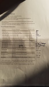
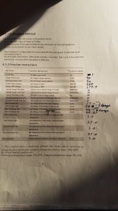
Hi Paul and anyone else interested I've now fitted my third-party dalley BMS 48-volt 14 string 60 amp to my GBL I 5001 I've had a lot to learn with getting the settings right as I opted for the standard plug and play vms without smart function but now happy to say it's working really well i thought i'd share some settings with you see attached photo with attention to voltage battery charge and discharge low and high settings for the charge it seems that this is a range that voltage fluctuates briefly in and out of of the same for discharge voltage fluctuates in and out briefly until discharge and charge functions are satisfied so in other words it's a range see my notes on my settings the charging up has worked really well today day got 3.4 kilowatt hours to 57v and 100% charge according to the display
DAY 5 : After 8 hours charging today the voltage on the battery is up to 3.65 per cell (51.5V). Reconnected the SP2000 to it , turned on the battery and the light is solid green :love: BUT the sp2000 is goosed. PV input is just sat at 2V. Think i might have a crack at creating my own SP2000 with an arduino, I've got a spare one somewhere. I've got current sensors, boost converters, I can monitor the grid power, I've got the charge cycle for the boston 5300 , How hard can it be :oops: Found a guy on youtube with the same boost converter as I've got
, I just need to adjust the power the same way the SP2000 does so I'm not drawing from the grid when charging, which I should be able to do in the arduino code. Just wondering whether I could get away with keeping the existing BMS , wonder what'd happen if I left the BMS connected , then connected the 3rd party charger ?


View attachment 112870
Hi I've just finished installing my daly bms 14s 48v 60a plug and play bms without smart function and I've had much deliberation with the growatt settings but think I finally got it tuned as best I can, see attached photo for my settings
The controller has managed to put 3.4 kW hours of charge into the battery today up to 57 volts at 100% just waiting to see what will happen this evening with discharging20220923_175526.jpg20220923_180752.jpg
 
Last edited:
DAY 5 : After 8 hours charging today the voltage on the battery is up to 3.65 per cell (51.5V). Reconnected the SP2000 to it , turned on the battery and the light is solid green :love: BUT the sp2000 is goosed. PV input is just sat at 2V. Think i might have a crack at creating my own SP2000 with an arduino, I've got a spare one somewhere. I've got current sensors, boost converters, I can monitor the grid power, I've got the charge cycle for the boston 5300 , How hard can it be :oops: Found a guy on youtube with the same boost converter as I've got
, I just need to adjust the power the same way the SP2000 does so I'm not drawing from the grid when charging, which I should be able to do in the arduino code. Just wondering whether I could get away with keeping the existing BMS , wonder what'd happen if I left the BMS connected , then connected the 3rd party charger ?


View attachment 112870
Hi Paul and anyone else interested I've now fitted my third-party dalley BMS 48-volt 14 string 60 amp to my GBL I 5001 I've had a lot to learn with getting the settings right as I opted for the standard plug and play vms without smart function but now happy to say it's working really well i thought i'd share some settings with you see attached photo with attention to voltage battery charge and discharge low and high settings for the charge it seems that this is a range that voltage fluctuates briefly in and out of of the same for discharge voltage fluctuates in and out briefly until discharge and charge functions are satisfied so in other words it's a range see my notes on my settings the charging up has worked really well today day got 3.4 kilowatt hours to 57v and 100% charge
Just to be a bit clearer the voltage battery charge high and low settings I believe this to be a range that the battery starts the stop charging process if that makes sense! And likewise for the voltage battery discharge low and high settings I believe this is a range that the battery starts the stop discharging process
and after discovering the anderson plug problem I have now increased the power to 95% and now no more tripping out !?

20220923_175526.jpg20220923_180752.jpg
 
Last edited:
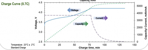
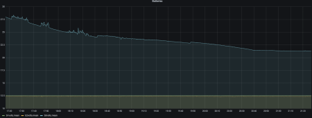
Nice work Tad, so that's in lead acid mode is it ? 'm a bit worried about my battery now. I've been charging it up without a BMS ,during the day, every day except Thursday as I had to go into the office. Don't worry, I played the role of the BMS and kept checking each cell, it was remarkably well behaved, every cell remained within 20mV of each other. Now it's only a 150W charger, so by the end of Friday I'd only got it up to 3.8V per cell, so I thought I'd try plugging it into a 1kw inverter and see how much I could get out of it. It worked fine for 2.5 hours until each cell was 3.42 volts, then it struggled to deliver 1KW ! from 3.4V down to 3.3V it was only outputting a few hundred watts, I disconnected it at 3.3V. Does that sound about right for these batteries or does it have a problem? .... here's the voltage chart , figure is offset by 25V as I still had 2 lead acid batteries connected to the monitor (long story) so e.g. 24V is really 49V .
1664012297999.png
 
Could someone do me a favour and buzz out the PV & Inverter connections on a working SP2000 ? On my faulty one theres 364 ohms between PV+ and PV- , and PV- is shorted to INVERTER+ ??? smells fishy
 
Nice work Tad, so that's in lead acid mode is it ? 'm a bit worried about my battery now. I've been charging it up without a BMS ,during the day, every day except Thursday as I had to go into the office. Don't worry, I played the role of the BMS and kept checking each cell, it was remarkably well behaved, every cell remained within 20mV of each other. Now it's only a 150W charger, so by the end of Friday I'd only got it up to 3.8V per cell, so I thought I'd try plugging it into a 1kw inverter and see how much I could get out of it. It worked fine for 2.5 hours until each cell was 3.42 volts, then it struggled to deliver 1KW ! from 3.4V down to 3.3V it was only outputting a few hundred watts, I disconnected it at 3.3V. Does that sound about right for these batteries or does it have a problem? .... here's the voltage chart , figure is offset by 25V as I still had 2 lead acid batteries connected to the monitor (long story) so e.g. 24V is really 49V .
View attachment 113268
Is that a 48 volt inverter that you have as it could be 3 3v x 14 is 46.2 V which might make it struggle and yes I'm setup for lead acid mode now have noticed a problem with the battery cutting out on charge and discharge I think it's one of two things voltage range in compatibility leading to not being able to get maximum charge and or discharge within reason or these daly boards arent quite the right amperage somehow i need to talk to Josh Cliff Jones as I believe he has set up for 80 amp BMS I still wonder if I should be looking for 52 volt BMS instead of 48v
 
Last edited:
Is that a 48 volt inverter that you have as it could be 3 3v x 14 is 46.2 V which might make it struggle and yes I'm setup for lead acid mode now have noticed a problem with the battery cutting out on charge and discharge I think it's one of two things voltage range in compatibility or these daly boards arent quite the right amperage somehow i need to talk to Josh Cliff Jones as I believe he has set up for 80 amp BMS
It's one of these , https://www.ebay.co.uk/itm/15501125926 , I set the bottom limit to 44.8V (3.2per cell) but ended up disconnecting at 3.3.
 
Hi Paul and anyone else interested I've now fitted my third-party dalley BMS 48-volt 14 string 60 amp to my GBL I 5001 I've had a lot to learn with getting the settings right as I opted for the standard plug and play vms without smart function but now happy to say it's working really well i thought i'd share some settings with you see attached photo with attention to voltage battery charge and discharge low and high settings for the charge it seems that this is a range that voltage fluctuates briefly in and out of of the same for discharge voltage fluctuates in and out briefly until discharge and charge functions are satisfied so in other words it's a range see my notes on my settings the charging up has worked really well today day got 3.4 kilowatt hours to 57v and 100% chargeView attachment 113172View attachment 113177
Also wow tip of the day clean the terminals in side the Anderson plug this has made a huge difference to how quickly charge and discharge starts am very tempted to fit a new plug now .what a difference!
 
Last edited:
I feel certain that some of these batteries with the original BMS boards could have been kept had there have been this knowledge especially regarding the Anderson plug also just a note in the future I will definitely be getting 52 volt BMS and not 48 as I believe this is the right way to go
a solar storage battery think of it like a boiler it needs maintenance and service every year or so so growatt and all manufacturers should realise this!
 
Last edited:

diy solar

diy solar
Back
Top