


You are using an out of date browser. It may not display this or other websites correctly.
You should upgrade or use an alternative browser.
You should upgrade or use an alternative browser.
DC Circuit Breaker for Hybrid Inverter
- Thread starter hgg
- Start date
Yes, using the same principle 1 leg has to be unconventionally wired.Ok, I see.
"How do you wire it right as a 2 leg ( + & -) MCB bi-directional current setting?"
You tell me... Is it possible?
But test it, you don't want to be second-guessing a manufacturer who has already second-guessed the consumer and made a non-polarized MCB.
Last edited:
hgg
New Member
- Joined
- Sep 5, 2022
- Messages
- 41
I'd better connect only the positive wire to the breaker and use a fuse as well.
I need the negative always connected because I will also use another switch
parallel to the positive connection together with a 20 Ohm power resistor
to precharge the inverter capacitors before switching on the battery.
I need the negative always connected because I will also use another switch
parallel to the positive connection together with a 20 Ohm power resistor
to precharge the inverter capacitors before switching on the battery.
hgg
New Member
- Joined
- Sep 5, 2022
- Messages
- 41
Ok, now I am confused! 
Just found a site that was selling this DC breaker and it says:
"This is a non-polarized circuit breaker, the input and output directions
of the circuit breaker can be interchanged. Suitable for 12V, 24V,
and 48V Battery Systems up to 600V DC Maximum."

 imexsolar.lk
It's the only place I found that it says its a non-polarized circuit breaker.
Chinese specs?...
Is there a way to find out if you have a non-polarized one?
(without burning it... )
Just found a site that was selling this DC breaker and it says:
"This is a non-polarized circuit breaker, the input and output directions
of the circuit breaker can be interchanged. Suitable for 12V, 24V,
and 48V Battery Systems up to 600V DC Maximum."
125A Non-Polarized DC MCB Battery Isolator TOMZN | IMEX Solar
2 Pole DC Circuit Breaker 125A DC MCB TOMZN in Sri Lanka for Residential Off Grid Solar Systems. Purchase yours now from IMEX Solar Energy Pvt Ltd.
It's the only place I found that it says its a non-polarized circuit breaker.
Chinese specs?...
Is there a way to find out if you have a non-polarized one?
(without burning it...
)Ok, now I am confused!
Just found a site that was selling this DC breaker and it says:
"This is a non-polarized circuit breaker, the input and output directions
of the circuit breaker can be interchanged. Suitable for 12V, 24V,
and 48V Battery Systems up to 600V DC Maximum."
125A Non-Polarized DC MCB Battery Isolator TOMZN | IMEX Solar
2 Pole DC Circuit Breaker 125A DC MCB TOMZN in Sri Lanka for Residential Off Grid Solar Systems. Purchase yours now from IMEX Solar Energy Pvt Ltd.
It's the only place I found that it says its a non-polarized circuit breaker.
Chinese specs?...
Is there a way to find out if you have a non-polarized one?
(without burning it...
I'll relate my experience...
I bought sample MCBs from China also with the same non-polarized description, but also with the same + and - markings.
A 32A and a 125A sample.
I corresponded with the salesperson about my suspicions and we came to an understanding that I would test them and if they burnt out he would refund me.
I received said MCBs and initially tried to establish with a piece of iron if I could feel a magnetic force externally.
I couldn't.
I have test equipment so I then repeated the on-load video test bi-directionally and they passed.
I then simulated fault conditions bi-directionally and they could also trip independently and clear the simulated overload.
So I still remain none the wiser if you could actually feel the force of the magnet externally on an actual polarized MCB, as mine are non-polarized.
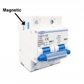
A non-polarized MCB doesn't use a magnet as far as I know.Just test it with a steel flat ruler and it is indeed magnetic in both sides,
upper rear side part near the pin hole. The ruler almost sticks to it.
Does this mean that its actually polarized?
hgg
New Member
- Joined
- Sep 5, 2022
- Messages
- 41
One last question. This is a two pole breaker switch. I suppose it has two arc diverters,
one in each pole. If I connect it like you said in order to work bi-directionally for a single
line, when the left arc diverter works properly during switching under load, wouldn't the
other arc diverter repel the arc instead of attracting it ??? Like half the unit working?
one in each pole. If I connect it like you said in order to work bi-directionally for a single
line, when the left arc diverter works properly during switching under load, wouldn't the
other arc diverter repel the arc instead of attracting it ??? Like half the unit working?
There will be no current in the circuit to start a fire if the first half does its job.But then the other half might start a fire!
But like I said prove it by testing, don't take some random guy's opinion over the internet when your house could burn down.
hgg
New Member
- Joined
- Sep 5, 2022
- Messages
- 41
Current will be passing through both sides simultaneously.
During the disconnect, arcs will be created in both chambers.
The same time one side quenches the arc, the other will divert it
away from the quencher. So maybe there will be a small damage
to the other side which will become worse every time you
open the switch.
I think that polarized breakers are not suitable for hybrid inverters.
Maybe I will use is simply as a PV disconnect switch.
Hedges
I See Electromagnetic Fields!
- Joined
- Mar 28, 2020
- Messages
- 20,753
The bi-metalic part will still save the day, but s l o w l y.
DC breakers are not perfect but still way better than nothing.
Bi-metallic would be thermal slow trip.
Magnetic is fast trip.
There are many thermal-magnetic breakers (AC breakers are typically this type), which tolerate an inrush up to say 5x or 10x rated current for a short time. seconds to minutes or an hour, depending on how much above the thermal trip limit. Beyond that 5x or 10x, they trip in 100's or 10's of milliseconds.
Magnetic-hydraulic breakers have a temperature-independent slow trip, 100's of milliseconds to minutes. And a fast trip.
Polarized DC breakers have a permanent magnet, not to trip in one direction, but to blow out the arc (into arc chutes where they cool). Reverse polarity, they still trip but can burn.
I think non-polarized breakers use a coil, an electromagnet, to blow the arc into chute regardless of direction of current flow.
You can get non-polarized breakers up to 175A or 250A, with 50,000 AIC (fault current interrupt capability) from Midnight. Stella Volta and other resellers have them.
Last edited:
hgg
New Member
- Joined
- Sep 5, 2022
- Messages
- 41
Can something like this disconnect the battery under load without any problems?

 energymonkey.co.uk
Blue Sea m-Series Mini On-Off Battery Switch with Knob - Red (BS6006)
Blue Sea m-Series Mini On-Off Battery Switch with Knob - Red (BS6006) Switches a single battery to a single load group Ignition protected - safe for
energymonkey.co.uk
tigerwillow1
Solar Enthusiast
- Joined
- Sep 20, 2021
- Messages
- 194
I couldn't find in the video what the voltage creating the arc in the breaker is. Was it there and I missed it? I suspect that's just as big a factor as the current.
Vigo
Solar Addict
Not likely. It claims a max voltage of 48, which means any actual 48v system would exceed it. I would guess it is internally identical to all the similar devices for lower voltage systems, which means it's not going to put enough of a gap in between the contacts to extinguish an arc from a battery system that can flow a couple thousand amps or more.Can something like this disconnect the battery under load without any problems?
Blue Sea m-Series Mini On-Off Battery Switch with Knob - Red (BS6006)
Blue Sea m-Series Mini On-Off Battery Switch with Knob - Red (BS6006) Switches a single battery to a single load group Ignition protected - safe for
It could be used as a disconnect under low/no load IF it didn't have an unacceptable voltage drop, high load is very iffy and would probably not do it many times without burning up the contact points if it even worked the first time, and could not really be considered a safety item.
This has been a cool thread, i've learned some things already!
You'd do well to notice these symbols on your switchgear:Can something like this disconnect the battery under load without any problems?
Blue Sea m-Series Mini On-Off Battery Switch with Knob - Red (BS6006)
Blue Sea m-Series Mini On-Off Battery Switch with Knob - Red (BS6006) Switches a single battery to a single load group Ignition protected - safe for
They are important to identify what equipment is rated for what purpose.
Note: Not all switches are rated to break load current and not all circuit breakers provide adequate isolation.

hgg
New Member
- Joined
- Sep 5, 2022
- Messages
- 41
@Vigo The switch will see from my battery bank 28V max, so the 48V rating might be adequate.
It also has a rating of 300A continuous which is 3 times the 100A max of my setup.
Interestingly, if you have a look at back side of the switch the two studs are marked Input / Output. (?)
@Phil.g00 Useful, thanks.
Ok, in the operating instruction the say:
"Turn all appliances off before turning the battery switch to OFF."
 www.bluesea.com
So, no switching under load... :-(
It also has a rating of 300A continuous which is 3 times the 100A max of my setup.
Interestingly, if you have a look at back side of the switch the two studs are marked Input / Output. (?)
@Phil.g00 Useful, thanks.
Ok, in the operating instruction the say:
"Turn all appliances off before turning the battery switch to OFF."
m-Series Mini On-Off Battery Switch with Knob - Red - Blue Sea Systems
300 Amps continuous rating for outboards and small gasoline or diesel engines.
www.bluesea.com
So, no switching under load... :-(
Hedges
I See Electromagnetic Fields!
- Joined
- Mar 28, 2020
- Messages
- 20,753
And you even considered switching it under load?
It is entirely manual, no spring-loaded snap action.
Arc weld much?
That link is a 2-position switch. If you get a 3-position, should be good for capacitor precharge.
If you want to disconnect under load, something like this should be good.
Add a precharge pushbutton and resistor.
It is entirely manual, no spring-loaded snap action.
Arc weld much?
That link is a 2-position switch. If you get a 3-position, should be good for capacitor precharge.
If you want to disconnect under load, something like this should be good.
Add a precharge pushbutton and resistor.
Similar threads
- Replies
- 23
- Views
- 884
- Replies
- 16
- Views
- 577
- Replies
- 2
- Views
- 166
- Replies
- 4
- Views
- 258