diy solar

diy solar

DC water heater.

I would like to see someone do this and report back. It would be good info. But........

I know this thread is going all over the place but I just want to add a concept that gets told over and over again. Heating elements are rated for a voltage and as your voltage drops or raises, the element output will change non linear to the voltage change.

Example; A 2400w 240v element will put out 600w at 120v. That is 1/4 the output. So make sure you match this. I'm using 4800w 240v elements at 120v(1200w).

Your panel voltage will change depending on light conditions/temperature and you will have a mismatch and may get very low output except on those perfect conditions.

If I was going to do this, I would pickup a cheap MPPT and make a string of panels. I would then build a circuit on a timer to turn on the charge controller in the morning(battery simulator) and then a switch to turn on the load. This would be clunky.

Someone started building a specific hot water controller but it never took off. I would buy one if someone made one less then $500.

Another option would be an PWM load diversion controller but that will require panels in parallel and similar voltage to elements. It would not work good in low light. I guess one could run an MPPT controller from the panels and just set a load diverter to a slightly lower charge voltage.

Of course some of these ideas goes into the lower voltage range 12v-48v which creates high amperage issues
Thank you. This is what I was looking for. Along with the others that have helped with this kind of information. I really didn't want to get into a debate whether this would work or not. I ran through all of the possibilities. And it's either panels powering DC elements. Or solar hydronic panels. The later being way too expensive. If bought new. But now I have to see if I could get used hydronic panels.
Thanks again everyone.
Or DIY and build your own water solar panels, not too hard to do. Guys have even used cpvc in the collectors before, it would work for you as you only need it in winter. Google is your friend it you want to save cash.
 
Or DIY and build your own water solar panels, not too hard to do. Guys have even used cpvc in the collectors before, it would work for you as you only need it in winter. Google is your friend it you want to save cash.
I did a deep dive a while back trying to figure out a way to build thermal panels without breaking the budget. Issue was, all the cheap materials options are not able to survive a high temperature "event". In the end, the cheapest system I could design was and air over water. That is, they where cheap air heaters( the window screen style) and the air was blown over a radiator/heat exchanger to heat water. The cool thing about the design was the water was not outside so less freezing issues. Also, the option of heating living space with air being available.
 
I did a deep dive a while back trying to figure out a way to build thermal panels without breaking the budget. Issue was, all the cheap materials options are not able to survive a high temperature "event". In the end, the cheapest system I could design was and air over water. That is, they where cheap air heaters( the window screen style) and the air was blown over a radiator/heat exchanger to heat water. The cool thing about the design was the water was not outside so less freezing issues. Also, the option of heating living space with air being available.
He would not need them in a high temp situation, no need for this in summer, cover it up, wait till winter, lol.
 
If your water heater has two heating elements, you can make a controller to somewhat optimize the results. Say each element is 4 KW at 240 VAC. Each element will be 4 KW at 240 VDC as well. This works out to 14.4 ohms (ignoring temperature effects, which can be significant).

Say you have a 10 KW array which peaks at 270 volts and 37 amps. This slightly overdrives both elements in parallel but I suspect that will be tolerable.

If the output decreases, disconnect one element which transfers better power than leaving both in and lowering array voltage.

If the output decreases even further, put the elements in series.

In this way, you have 3 possible load matches to the array thus can crudely optimize the energy transfer.

A precise modeling of the heater element and the array would determine appropriate crossover points between the various configurations.

Mike C.
 
240 AC is not equivalent to 240v DC. The resulting power output will not be the same. 240AC equals about 170v DC.
 
240 AC is not equivalent to 240v DC. The resulting power output will not be the same. 240AC equals about 170v DC.
Please lookup RMS (root mean square) voltage.


240 VAC driving a resistive load has exactly the same power delivery of 240 VDC driving that same load. The example they give happens to be exactly 240 VAC.

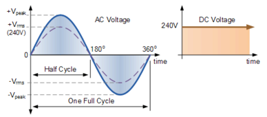
"For example, the domestic mains supply in the United Kingdom is 240Vac. This value is assumed to indicate an effective value of “240 Volts rms”. This means then that the sinusoidal rms voltage from the wall sockets of a UK home is capable of producing the same average positive power as 240 volts of steady DC voltage as shown below."

1710816589255.png

Vpeak of 240 VAC RMS is 339 volts.

I don't charge tuition, but the education is just as good.

Mike C.
 
Please lookup RMS (root mean square) voltage.


240 VAC driving a resistive load has exactly the same power delivery of 240 VDC driving that same load. The example they give happens to be exactly 240 VAC.

"For example, the domestic mains supply in the United Kingdom is 240Vac. This value is assumed to indicate an effective value of “240 Volts rms”. This means then that the sinusoidal rms voltage from the wall sockets of a UK home is capable of producing the same average positive power as 240 volts of steady DC voltage as shown below."

View attachment 202965

Vpeak of 240 VAC RMS is 339 volts.

I don't charge tuition, but the education is just as good.

Mike C.
Vpeak * sqrt(2) / 2 = Vrms. It's trig, calculating the area under the curve to get the mean voltage for the cycle of a sine wave.
 
Vpeak * sqrt(2) / 2 = Vrms. It's trig, calculating the area under the curve to get the mean voltage for the cycle of a sine wave.
Close, it is the mean square voltage of a sine wave. Power is V^2/R, so the power tracks with the square of the voltage.

That's is why it is called RMS, root mean square. First, you square the sine wave, then you take the average (mean), and then you take the square root of that. It is the root of the mean of the square, thus RMS.

What this does is present AC voltages in a way that makes them comparable to DC voltages. 240 VAC and 240 VDC into the same resistive load produces the same average power transfer.

If we express AC voltage in peak, we'd have all sorts of trouble figuring out power. With voltage and current expressed in RMS, take RMS voltage times RMS current and you get power (well, assuming purely resistive loads, reactive loads change things).

Mike C.
Uh huh, x^2 + y^2 = 1 is the unit circle from which trig functions are derived. AC is created by spinning a magnet 360 degrees inside a coil creating a sine wave. It's been a very, very long while, but it's still trigonometry expressed as root mean square. sin^2(a) + cos^2(a) = 1 and off you go into everyone's favorite math . . . !$#@! trig.

Your spot on point of course is that you read RMS from AC not peak, and resistors do not care if it's AC or DC.

You can have fun with AC-DC conversion using the pulses to trigger a stepper to charge up capacitors in sequence increasing voltage, with a corresponding decrease of available current, switching power supplies, blah, blah but optimally a simple bridge and load side cap on AC should net the same voltage and current capacity DC as AC under the rated load. The DC voltage will be much higher without a load, and is generally regulated to prevent this if it matters. Modern IC's perform black magic to make all this happen these days.
 
If your water heater has two heating elements, you can make a controller to somewhat optimize the results. Say each element is 4 KW at 240 VAC. Each element will be 4 KW at 240 VDC as well. This works out to 14.4 ohms (ignoring temperature effects, which can be significant).

Say you have a 10 KW array which peaks at 270 volts and 37 amps. This slightly overdrives both elements in parallel but I suspect that will be tolerable.

If the output decreases, disconnect one element which transfers better power than leaving both in and lowering array voltage.

If the output decreases even further, put the elements in series.

In this way, you have 3 possible load matches to the array thus can crudely optimize the energy transfer.

A precise modeling of the heater element and the array would determine appropriate crossover points between the various configurations.

Mike C.
Kool thank you this is what I was looking for. The best way to set up the PV system. I have a good handle on the hydronic heating. Would use drain back system. PV panel to run pumps. If I can find a good deal on atleast 10 used panels. But leaning towards PV.
 
Combine the water heater heat pump with a fridge or freezer on the other end then you have a winner.
Freezer is 2 feet away and propane water heater is also a few feet away. The inverters and charge controllers are also there so any heat generated gets recycled. Using the heat pump water heater for domestic hot water with solar for power works great. I'm very impressed, with the phone app allowing remote control and having propane as backup in times of low PV yield works very well.
 
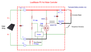
You can use PWM DC into an immersion heater/s. I'll dig out the approach
Basically a buck switching voltage regulator that allows the panels to be higher voltage (and thus more power) than the load. The power output could be kilowatts so this is a non trivial power supply design.

If the schematic present is representative, this thing probably radiates electrical noise like crazy out of the PV wires. Capacitor C1 needs to be hefty and rated for the ripple current it will see, too.

Very easy to build this badly and blow up MOSFETs, radiate noise, cause ringing, etc.

If you do the 2 element, 3 step parallel, single, series trick I mentioned earlier, you probably get 90% of the benefit of this circuit for a lot less effort.

Mike C.
 
All of this discussion, and unless I missed it, there’s no good solution to the fact that the thermostat is rated for AC, and will probably arc and short when used on DC. Why not make AC with all of your panels, and use as much as you need to for making hot water, and use the rest of it elsewhere?
 
All of this discussion, and unless I missed it, there’s no good solution to the fact that the thermostat is rated for AC, and will probably arc and short when used on DC. Why not make AC with all of your panels, and use as much as you need to for making hot water, and use the rest of it elsewhere?
If DC switching is wanted, one could use these. https://batteryhookup.com/products/te-connectivity-ev200aaana-500a-0-900vdc I recently purchased 24 of them and plan to use these to switch PV from one system to another remotely. I can't find any type of transfer switch to do what I want so I'm building my own. These do require a power supply less than 36V.

Use the AC thermostat to control the HV relay. The AC thermostat should be able to switch a 12V load at 0.13A.
 
Back
Top