AgroVenturesPeru
New Member
- Joined
- Sep 19, 2020
- Messages
- 411
Hello again forum,
I'm about to move off-grid, and trying to figure out how to put all my components together. I bought a custom kit from Novum Solar here in Peru based on my wants/needs.
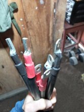
I think they sent about 90% of everything I need to put the system together (they told me that I had better buy certain things on my own, once I know the measurements and configuration of where I will be doing the installation... One question I have is about the cables.
On the roof there will be 12, 400w panels arranged in 4s3p
Each string producing ~196V and ~10.5A will go to a combiner box for paralleling the strings, and, from there, output roughly 196v and 32 amps.
I've got 4mm squared wire for the roof to the combiner box (max distance on one string is 5m from the combiner box). I'm also thinking I can get away with using the same 4mm-squared size wire from the combiner box to the charge controller (about one meter of length).
The charge controller is a Victron MPPT 250/100 with screw terminals.
Does anyone know how to calculate what the MPPT charge controller does to the 196v and 32amps that enter it? I know the MPPT lowers the volts and increases the amps, but I don't know exactly to what degree nor how many amps will be coming out of the MPPT. Is that programmable?
Battery bank:
4, LiFePo4 batteries wired in parallel. Each one is 48v and 74ah.
The manufacturer of the batteries says not to exceed a charge/discharge current of 37A on each battery for warranty purposes.
Basically I just want to know what is the correct wire thickness from MPPT to battery bank (assuming the distance between the two is less than 1 meter or 3.2ft) in this situation. Please advise. I did a number of internet searches before asking here.
Edited to add:
I should have mentioned that Vmp = 40.16V
and Imp = 9.96A
to be more precise.
I'm about to move off-grid, and trying to figure out how to put all my components together. I bought a custom kit from Novum Solar here in Peru based on my wants/needs.
I think they sent about 90% of everything I need to put the system together (they told me that I had better buy certain things on my own, once I know the measurements and configuration of where I will be doing the installation... One question I have is about the cables.
On the roof there will be 12, 400w panels arranged in 4s3p
Each string producing ~196V and ~10.5A will go to a combiner box for paralleling the strings, and, from there, output roughly 196v and 32 amps.
I've got 4mm squared wire for the roof to the combiner box (max distance on one string is 5m from the combiner box). I'm also thinking I can get away with using the same 4mm-squared size wire from the combiner box to the charge controller (about one meter of length).
The charge controller is a Victron MPPT 250/100 with screw terminals.
Does anyone know how to calculate what the MPPT charge controller does to the 196v and 32amps that enter it? I know the MPPT lowers the volts and increases the amps, but I don't know exactly to what degree nor how many amps will be coming out of the MPPT. Is that programmable?
Battery bank:
4, LiFePo4 batteries wired in parallel. Each one is 48v and 74ah.
The manufacturer of the batteries says not to exceed a charge/discharge current of 37A on each battery for warranty purposes.
Basically I just want to know what is the correct wire thickness from MPPT to battery bank (assuming the distance between the two is less than 1 meter or 3.2ft) in this situation. Please advise. I did a number of internet searches before asking here.
Edited to add:
I should have mentioned that Vmp = 40.16V
and Imp = 9.96A
to be more precise.
Last edited: