diy solar

diy solar

Deye weird zero export to CT behavior

Vjv

New Member
Joined
Feb 6, 2022
Messages
5
Very new to this. I had my PV and inverter installed last year and I'm just trying to get optimal usage out of it. My installer is not familiar with any of the advanced features if the inverter, they include it just for critical load/battery backup.

The objective is to get the inverter to *not* charge the battery from solar when there's an active household load (loads not on my critical loads transfer switch). I discharge the battery overnight so I buy less grid power, and it starts charging as soon as the sun comes up. But I *don't* want it to charge if, say, I run my AC or car charger (not on the hybrid inverter). My understanding is that this is "zero export to CT" mode. But, when I activate this mode, the readouts don't make any sense.

224 (2).jpg 224 (1).jpg

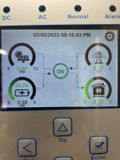
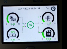
I've attached some pictures from the middle of the day with not much demand in Zero Export to CT mode. From the photos you can see it reports a 5kw load, but in reality it's probably more like 1kw. And for whatever reason it is drawing from the battery even though the 4kw of solar coming in is plenty for everything. My sense energy monitor and AP systems portal are in agreement about my solar production, but it sees the solar input as a load?

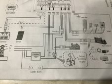
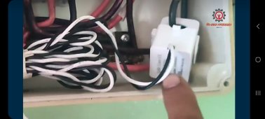
RIght now I've got the CTs installed on grid side of the main breaker. I've also tried having them installed on the grid connection at the inverter itself, which more or less produces the same behavior.

224.jpg

I suspect this is due to the way that things are wired connected at my MSP, but I'm not sure how to resolve it. Or maybe it's because I'm using the grid input as my solar input (manuals say this is correct, but maybe the SW doesn't like it.)

224 (3).jpg224 (4).jpg
 
Last edited:
I am not familiar with your inverter but the way CT determines power flow direction is by not only the amplitude but also the phasing relationship between AC voltage and AC current.

If either the current sense transformer or the AC voltage sense pairs are reversed the power flow direction will be interpreted wrong. Since the voltage sense is tied to inverter's L1/L2 connection, the CT sensor is most likely to be reversed. This includes putting the AC line wire through the toroid from the wrong side.

If you are operating 240/120v split phase, each 120vac side must be correct for their respective sensor phasing. It is possible to have one 120 vac side correct and the other 120vac side wrong.
 
Last edited:
Thank you! The flipped the CTs and now the inverter reports total consumption of backed up and non backed up loads when I have zero export to CT active. Tomorrow morning when my car charger kicks on we'll see if it charges the battery or the car.
 
Thank you! The flipped the CTs and now the inverter reports total consumption of backed up and non backed up loads when I have zero export to CT active. Tomorrow morning when my car charger kicks on we'll see if it charges the battery or the car.

That looks like the inverter I have as well, and I am trying to do the same thing. How do you see the total consumption of backed up and non backed up loads? I do have zero export to CT active. Am I also supposed to have Solar Sell checked?
 
Thank you! The flipped the CTs and now the inverter reports total consumption of backed up and non backed up loads when I have zero export to CT active. Tomorrow morning when my car charger kicks on we'll see if it charges the battery or the car.
Hi want asking you if helpfull to point ct direction Grid?
 
@HarrySoen , on page 20 of the attached manual will show you how it need to be connected for Europe.
A picture from me will do you no good because I'm having a split phase connection with 2 CT's
If you want to see consumption you need to install the CT.
 

Attachments

  • User Manual of deye 5-8kw hybrid.pdf
    6.3 MB · Views: 66
Thank u for ur reply.
I hve 3 phase 8kwh inverter. Use the grid fysiek connection and goes to meter in the basement is about 30M, is inconvenience to install the CT. So i install the CT at the the phase after the cable connection from the inverter (grid).
 

Attachments

  • Screenshot_20230302_192604_Facebook.jpg
    Screenshot_20230302_192604_Facebook.jpg
    509.7 KB · Views: 41
So i install the CT at the the phase after the cable connection from the inverter (grid).
I'm afraid that is not working.
You have to install before the connection make from the inverter to the grid.
Not familiar with 3 phase but my gut tells me that you need 3 CT's.
30 meter is a long way I asked Deye if I can extend the leads of the CT's and they advised against it.
A member on here (can remember who) did have a similar problem and did something with a power mete and Cat6 cable maybe a search on this forum can help you with that.
 
When using the Deye inverter, I also encountered a problem.
I set zero outlet to CT, load first mode.
When the battery is fully charged, it will automatically discharge, although at this time the power of the load and the export grid is greater than the PV power, but normally i would expect that the Inverter will decrease the Power fed to the grid so that PV - Load = Export. Thats my understanding of the System.
may I ask if this is normal?
 

Attachments

  • 微信图片_20230321181312.png
    微信图片_20230321181312.png
    342.1 KB · Views: 29
The location of inverter external CT sensor is the point where zero export point is defined. Usually if you are trying to avoid grid export you have to place CT sensors at the point where main grid cables enters main panel. This allows inverter to export to non-backed up loads in main panel when excess PV power is available.

All PV generated power has to be immediately consumed, either by AC loads, battery charging, or back feed through AC input. If you have CT sensor placed on grid input cables, with inverter set to no grid export and main panel loads, inverter AC output loads, and battery charging is less than available potential PV power, the PV charge controller will back down PV production by allow panel voltage rise toward Voc to back down PV production yield to match immediate total power consumption.

Normally AC output loads on inverter always take priority on consuming PV power. The inverter should back down PV used for charging battery if AC output loads are consuming power. When AC output load plus battery charging consume all available PV power there will be no back feed from inverter AC input port.

The inverter has additional CT sensors internal, at least on the actual inverter output stage node that are necessary to protect the inverter. Some inverters have additional CT sensors on AC input lines between actual inverter output stage node and AC input pass-through relay which are necessary for inverter to do AC input current load shaving. HF AIO inverters take a few milliseconds to switch inverter from charging battery and outputting AC from battery power.

For a HF AIO to do load shaving, they must have a large array of high voltage DC capacitors to carry the AC load during this battery to HV DC mode switching time. LF inverters are inherently bi-directional and can switch from charging to sourcing power from battery immediately. You are more likely to find load shaving feature on low frequency inverters because of this.

This HF inverter limitation on battery to HV DC power direction switchover time also creates risk of HF inverter damage when doing AC coupling of GT inverter to HF hybrid inverter. SolArk and Deye recommend using generator AC input port for AC coupling of a GT inverter giving them a safety disconnect of GT inverter if they get into trouble handling a sudden GT inverter overproduction situation when a large house load is switched off or grid dropout if exporting to grid.

There is also user functional control setting for use of grid or PV power priority for battery charging. Based on charger settings, this setting can hold off using grid for charging battery. It will still go to grid for required AC output loads when battery voltage gets too low and there is insufficient PV power available. Depending on menu naming convention, this can be confusing on how it actually works.

I believe in the Deye menu below, the difference between 'Zero Export to Load' and 'Zero Export to CT' is the difference between using the internal CT sensor in pass-through relay line and external CT sensor. Inverter uses one or the other and if you select internal CT sensor, zero export will be referenced to inverter AC input port so you will not supplement AC loads in main grid fed panel.
Deye setup copy.jpg

CT sensors are not super great in accuracy, so inverters usually hold a margin of error on zero export prevention. This may limit back feed to main panel loads when the external CT sensors on grid lines gets within a few amps of zeroing out incoming grid current to prevent measurement error from mistakenly allowing a small amount of export to grid.
 
Last edited:
The location of inverter external CT sensor is the point where zero export point is defined. Usually if you are trying to avoid grid export you have to place CT sensors at the point where main grid cables enters main panel. This allows inverter to export to non-backed up loads in main panel when excess PV power is available.

All PV generated power has to be immediately consumed, either by AC loads, battery charging, or back feed through AC input. If you have CT sensor placed on grid input cables, with inverter set to no grid export and main panel loads, inverter AC output loads, and battery charging is less than available potential PV power, the PV charge controller will back down PV production by allow panel voltage rise toward Voc to back down PV production yield to match immediate total power consumption.

Normally AC output loads on inverter always take priority on consuming PV power. The inverter should back down PV used for charging battery if AC output loads are consuming power. When AC output load plus battery charging consume all available PV power there will be no back feed from inverter AC input port.

The inverter has additional CT sensors internal, at least on the actual inverter output stage node that are necessary to protect the inverter. Some inverters have additional CT sensors on AC input lines between actual inverter output stage node and AC input pass-through relay which are necessary for inverter to do AC input current load shaving. HF AIO inverters take a few milliseconds to switch inverter from charging battery and outputting AC from battery power.

For a HF AIO to do load shaving, they must have a large array of high voltage DC capacitors to carry the AC load during this battery to HV DC mode switching time. LF inverters are inherently bi-directional and can switch from charging to sourcing power from battery immediately. You are more likely to find load shaving feature on low frequency inverters because of this.

This HF inverter limitation on battery to HV DC power direction switchover time also creates risk of HF inverter damage when doing AC coupling of GT inverter to HF hybrid inverter. SolArk and Deye recommend using generator AC input port for AC coupling of a GT inverter giving them a safety disconnect of GT inverter if they get into trouble handling a sudden GT inverter overproduction situation when a large house load is switched off or grid dropout if exporting to grid.

There is also user functional control setting for use of grid or PV power priority for battery charging. Based on charger settings, this setting can hold off using grid for charging battery. It will still go to grid for required AC output loads when battery voltage gets too low and there is insufficient PV power available. Depending on menu naming convention, this can be confusing on how it actually works.

CT sensors are not super great in accuracy, so inverters usually hold a margin of error on zero export prevention. This may limit back feed to main panel loads when the external CT sensors on grid lines gets within a few amps of zeroing out incoming grid current to prevent measurement error from mistakenly allowing a small amount of export to grid.
too add...
an external CT is much much more accurate.
i am using the Eastron SDM630 v2 MODbus
 
The supplied external CT sensor are no more accurate than internal CT sensor. Internal CT sensor is more likely to be calibrated to particular unit build than, a randomly selected from stock, external CT sensor put in shipping box with inverter.

Since an external CT sensor is more likely to get exposed to greater current, like 200A grid service feed, it is very important the CT sensor core size is sufficient to avoid saturating core at maximum AC current.

A CT sensor core can get biased from a sudden surge load saturating core to one side of magnetic B-H curve, like when grid drops out causing an inverter surge current overload, just for a moment, prior to pass-through relay releasing from grid.

Best accuracy AC current sensors are closed loop Hall effect sensors. They have a high frequency feedback loop op amp and additional winding on CT core to drive magnetic field in core to near zero.

This helps prevent saturation bias on magnetic core and keeps their accuracy over wide current range because magnetic field in core is held at low level. You won't typically find these more expensive sensors included with most inverters. They also would require a different inverter input interface design and external power supplied to their op amp.
i am not talking about the CT sensors ( or clamps) that came with the inverter, rather an external meter

 
Hi,

I am suffering with Deye CT settings and power export stuff. I tend to use Voltronic (VMIII 5K) off grid inverter which is very user friendly. I need some help in terms of CT settings (and other related settings) as I am moving from Voltronic to Deye 8KW (single phase, SUN-8K-SG01LP1-EU).

My usage scenario is as following:
The supply from the Power Company is not stable at all (frequent blackouts), and they don't support receiving energy. So my usage is essentially off-grid (though, I still need grid's power when available):
  • I need, when Company's energy is available, to use their power to supply my loads and charge battery (just same as Voltronic does).
  • When the Company's energy is down, the inverter shall automatically power all my loads (within its 8KW capacity).
  • The inverter should *NEVER* export any power back to the Company's lines (to grid) all the times, despite any available PV power.
  • If both grid and PV are available, PV should be the priority for loads and charging battery. If PV is not sufficient, then the inverter should use grid's power - just to keep bills to minimum.

Could you please guys tell me how to make CT connections and set of my Deye inverter to achieve the above (if possible at all!). Your help is much appreciated as I don't want to damage my inverter.

Thank you.
 
I also need help with my deye 8kW inverter. I have a solar system that is grid tied. I have batteries and deye that's plugged into a 50A outlet. I want to use the deye like a energy storage. Deye CT's are conencted to the main panel to sense power in/out. From 00:00 to 05:00, i set it up to charge from grid to 85%. From 09:00 to 16:05 I set it to maintain 85%. From 16:05 to 21:00, I want it to supplement the grid from battery as needed. If there's excess solar, use it to keep battery topped up. Then from 21:00 to midnight, use battery to power loads. Any one have suggestion on how to configure this on the deye?
 
Back
Top