diy solar

diy solar

DIY Battery via Smart shunt to inverter integration (Solis etc)

Hi @sijones2010 - I'm in the process of getting this set up for my Smart Shunt - this is great! Cant wait to get it up and running.

I'm running into an issue with the MQTT setup - I keep getting this error in my Home Assistant MQTT logs:
2023-12-10 03:25:57: Client vedirectmqtt already connected, closing old connection.
2023-12-10 03:25:57: New client connected from 10.0.1.112:55569 as vedirectmqtt (p2, c1, k15, u'emon').

Any idea why it keeps thinking its connected and reconnected?

I have MQTT running on other devices so I wasnt sure if thats what could be doing it.
 
Any idea why it keeps thinking its connected and reconnected?

I have MQTT running on other devices so I wasnt sure if thats what could be doing it.

That behaviour will happen when you have more than 1 client attempting to connect to your MQTT broker with the same client id.
 
Ok so I got it hooked up to my Victron smart shunt -

On the smart shunt app my battery SOC is 62%

On my MQTT in Home assistant it says:

Message 16744 received on SMARTBMS/SOC at 11:30 PM: 624

(I'm assuming 624 is 62.4%?)

But my inverter is reading the battery SOC is at 91 percent.

Do I need to do some sort of reset to get it get the correct SOC from the ESP device?
 
I got the ESP32 device to report SOC to the inverter, however Its seems to limit my charge current. My inverter can do 275A but when I use this device it caps out at 140A.

When I disconnect the ESP32 device and hook it up directly to my Seplos BMS CAN port - my inverter goes back to charging at 275A.

I've modified the settings here but still am getting this cap at 140A. Also I've tried to modify the charge voltage to 55.2 but it still only sends 56V to the inverter:
1704937440713.png

Perhaps there's somewhere else to change the charge current?
 
That's good you got it working. What is your SOC? The reason for asking is the code (intentionally) restricts the charge rate when the SOC is above 90% and further still when above 95%. You should be able to find the code if it exists in your version... it was written like this in the version I first adopted 18 months ago...

if (_battCapacity > 0){
if(_battSOC > 95)
_chargeCurrentmA = (_battCapacity / 18);
else if(_battSOC > 90)
_chargeCurrentmA = (_battCapacity / 10);
else
_chargeCurrentmA = _maxChargeCurrentmA;
}
 
Yes I noticed it does this at 90% but this cap at 140A is occurring at lower percentage (I’m was at 60%). Also my inverter keeps reading a charge voltage of 56V instead of 55.2V

I spoke with my inverter manufacturer (SolArk) and they said because the inverter is hooked up to battery via the CAN bus I can’t customize the charging voltage /amps on the inverter since that is provided by the battery to the inverter via CAN.

Is there a way to view what the chargecurrentMA value is on the esp32 device when it’s hooked up to the inverter ?
 
Last edited:
You could connect the ESP32's serial debug port to a laptop (running off batteries to avoid any ground loop) and add some debug to the code to see what values the code is sending to the inverter. Or add some logging to an MQTT input / whatever.
 
This is amazing...Thank you, thank you, thank you!

I have a SmartShunt that already publishes its values through MQTT (ICC Solar does this on an RPi4 that has the VEDirect USB attached).

So I have the values from the shunt on a mosquitto server, can I use this to feed my GoodWe SBP inverter with BMS data through its Canbus?

My SBP only charges at 60% amps because the battery is self defined i.e unsupported and the battery has no communication bus, just a dumb BMS that trips the battery breaker when it detects a fault.
 
So I have the values from the shunt on a mosquitto server, can I use this to feed my GoodWe SBP inverter with BMS data through its Canbus?
(y) with a bit of programming, sounds like a good plan - should be not too complex to modify this project to do that - then you can add to it and add finer control of the inverter to battery comms over CANBus.
 
Thanks, I have a ESP32-EVB-EA-IND that has a CAN transceiver and interface so that should be the hardware covered.

The programming is above my comfort level though, any ideas on how I could get this done, anyone had any luck with getting coding done on a platform like Fiverr?

MQTT subscribe mappings to a BMS values input would be a cool feature.
 
Last edited:
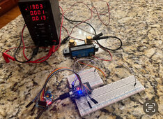
I’ve got this wired up on my bench power supply and see that it’s sending through the MCP2515 via serial ports log. I’ve had this running for well over a week this way and no failures in the debug logs. This Sunday will be connecting shunt and trying this out with a EG4 6000xp.

IMG_4729.jpeg

[2065819][CANBUS.cpp:205] SendBattUpdate(): Battery Charge Flags via CAN Bus sent.
[2065945][main.cpp:190] loop(): New block arrived; Value count: 17, serial 4129
[2066446][main.cpp:190] loop(): New block arrived; Value count: 13, serial 4130
[2066447][main.cpp:113] UpdateCanBusData(): Battery Voltage Update: 13043V
[2066449][main.cpp:119] UpdateCanBusData(): Battery Current Update: 0mA
[2066456][main.cpp:125] UpdateCanBusData(): Battery SOC Update: 987%
[2066827][CANBUS.cpp:60] SendAllUpdates(): Sending all CAN Bus Data
[2066828][CANBUS.cpp:304] SendParamUpdate(): Sent PYLONTECH String.
[2066833][CANBUS.cpp:333] SendParamUpdate(): Inverter Parameters update via CAN Bus sent.
[2066837][CANBUS.cpp:138] SendBattUpdate(): Inverter SOC Battery update via CAN Bus sent.
[2066850][CANBUS.cpp:160] SendBattUpdate(): Inverter Battery Voltage, Current update via CAN Bus sent.
[2066859][CANBUS.cpp:182] SendBattUpdate(): Inverter Protection / Alarm Flags via CAN Bus sent.
[2066868][CANBUS.cpp:205] SendBattUpdate(): Battery Charge Flags via CAN Bus sent.
 
Last edited:
@ChrisG Looks good! Just be careful you don't hit any ground loop issues when you connect it up like I did with my Solis. Maybe the EG4's battery -ve isn't at big potential difference to ground like the Solis inverters are. I find its OK if you connect the battery then the CANBus, but not the other way around... see more details in my thread here...
 
@ChrisG Looks good! Just be careful you don't hit any ground loop issues when you connect it up like I did with my Solis. Maybe the EG4's battery -ve isn't at big potential difference to ground like the Solis inverters are. I find its OK if you connect the battery then the CANBus, but not the other way around... see more details in my thread here...
@SeaGal I have custom built EVE packs with non inverter JK BMS’s. I will only be connecting CAN H/L to inverter from MCP2515. Goal is to control inverter via SOC/etc via shunt. Don’t expect a loop but thanks for mentioning it. Will find out Sunday and report back. This could be a game changer if this works using Victron shunt.

For now I will use a 5v usb charger from loads panel circuit to power the ESP/MCP. Will use a buck converter off battery in the future if this actually works.
 
Don’t expect a loop but thanks for mentioning it.
(y) fingers crossed it will work just fine. My controller, using code derived from the one from this thread, has been running really well for 18 months.

So the 'loop' I was referring to is because the MCP2515 module (specifically the TJA1050 transceiver) is not galvanically isolated. Hence there is a continuity between the CANBus L signal level and the ESP32's 0v, which in turn is connected to the SmartShunt's signal ground, which in turn is connected to the inverter's battery -ve.
Ahh, ok. Thank you for that detail (didn't read your thread link above yet ). I will dive into your thread to see how you handled that so I have something to 'try' if it doesn't work on initial setup.
 
@SeaGal Quick question, are you running the platformio.ini as debug:
build_type = debug
build_flags = -DCORE_DEBUG_LEVEL=3
 
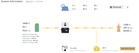
Ok, I have this working, but it seems to ignore the settings in the config.h file for charge current. Not sure why the charge current would be 100A when I have it set to 20A. I have the current limited in the inverter settings at the moment. This is really an awesome project, think I just need a few tweaks for my specific settings. On the EG4 6000xp (lux) I'm running LFP Battery Type 2 for Pylon.

1710175403516.png

1710175426337.png
 
Ok, I have this working, but it seems to ignore the settings in the config.h file for charge current. Not sure why the charge current would be 100A when I have it set to 20A. I have the current limited in the inverter settings at the moment. This is really an awesome project, think I just need a few tweaks for my specific settings. On the EG4 6000xp (lux) I'm running LFP Battery Type 2 for Pylon.

View attachment 201498

View attachment 201499
Interesting, SOC hit 90% and it lowered to my configured 20A charge
1710181744208.png
 
As I mentioned, my code is highly modified from the original, so this is a bit of a guess...

Trace through / log / debug where "_maxChargeCurrentmA" is set and used.

I suspect it might being overridden by the "initBattCapacity" / "_battCapacity" variable which is used to call the CAN_SetChargeCurrent() function.
Overall happy to report this is working. I may start another thread on this, know some others would be interested this project with the new EG4 Lux inverters that are out.
 
Back
Top