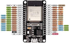
Did you mean this diagram?...
.
...if so, I don't know why that was posted in this thread, it is not useful.
The potential divider shown there is if you need to convert from a 5V input signal to the 3.3V of the ESP32; that is not needed for the Victron SmartShunt as it uses 3.3V signal already.
The 4K7 pull-up resistor shown in that diagram is for connecting a temp sensor like a DS18B20 using the Dallas OneWire interface - if you are don't need to measure temperature then you don't need that resistor.