diy solar

diy solar

DIY Battery via Smart shunt to inverter integration (Solis etc)

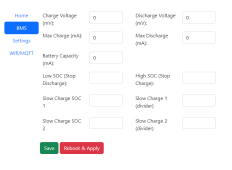
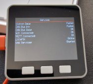
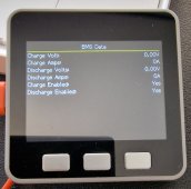
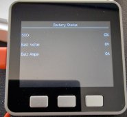
Quick peek to what's coming, the web page will work with the esp that is already in use, the display support requires an m5stack core or core 2.

And hopefully this release won't require any programming knowledge as you'll just be able to use the esp flasher and then configure everything after flashing!
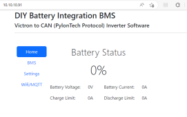
Screenshot_20230206_123437.png
Screenshot_20230206_123456.png20230206_123600.jpg20230206_123634.jpg20230206_123646.jpg
 
the solis rai 3k asks me all the time conect can, that's I have it configured for acid batteries, but the charge its slow and i think i will need this
 
....you don't want the BMS cutting off as this will trigger a error on the Solis of over voltage hardware.

...
Is that an issue?
Or should I read; if the BMS disables the charging the inverter also stops discharging?
 
Is that an issue?
Or should I read; if the BMS disables the charging the inverter also stops discharging?
The inverter will go in to alarm if your BMS disconnects the batteries, this can then mean the inverter won't use the batteries whilst it's in this state.
 
The inverter will go in to alarm if your BMS disconnects the batteries, this can then mean the inverter won't use the batteries whilst it's in this state.
I guess I just wanted to understand if the inverter can recover from such an error when the inverter later wants to take energy from the battery or if it needs manual intervention. But that is maybe something I need to check from a manual ;-).
Or also; I have to check what it means from the inverter when a BMS blocks charging or discharging (does it see overvoltage or just a high resistance).
The BMS will disconnect the power flow to the batteries, the draw will be available but the inverter if it's in alarm may not take any, no need for manual intervention as it will sort it self out but if I remember rightly while the alarm is in play the inverter stops until recovered i.e. battery is available.

It sees it as over voltage alarm.

It's looking at the soc and if lower than what you've set then it wants to send charge.
 
any tutorial for how i can put your software in the esp32?
There are many guides on line for installing Arduino code onto an ESP32, like this one for example...

Initially you will need to connect your ESP to your PC via its USB connector. Once the software is there, Simon's code supports OTA (over the air) updates, so future updates can be done over WiFi via your browser.
 
ok... so for those of you with a spare esp32 and want to experiment there is now a testing branch, this is the latest code but NOT production ready as am still fixing some bits and rearranging the code, it's a bit messy at the moment due to different ways of trying things, but thought those that want to see the changes can.

It requires 2 flashes to the device, install instructions on Github here, you don't need to change the config file for anything, all configured in the web browser.

Again, do not overwrite your esp that's in use with this, play with a spare.

esp32 is supported along with m5stack grey and core2 with a commu base are supported, will upload some pics once it's in place and working nicely.
 
Last edited:
Hello people, lots to read and learn, I appreciate all the contribution above.
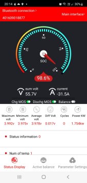
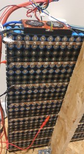
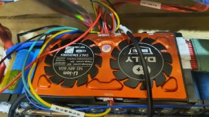
My Rai3K5g been delivering some 6 months ago and been collecting dust since then. However in the meantime i put together some 560 cells of 18650 and acquired 2x Daly 60A. The plan was to build 2x 90Ah packs but i won't do the second pack due to all time spent in building the first pack.
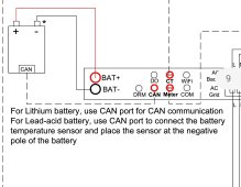
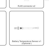
Anyway i learned in this time that Solis won't work properly without Can communication with a bms. I see you all use the smart shunt from victron. However my Solis manual lists a BTS optional cable which seems to be wired in Can port cable. I can't find that cable anywhere for Solis and the seller i bought this from didn't reply yet. I would be tempted to wire a temperature sensor on a data cable and test it, but need to do a bit of research for that, any ideas are welcomed.
System seems to work with Lead acid battery settings but voltages are not quite right.
Also i extended the CT clamp wires about 3 meters... some guys mentioned do not extended or shorten those wires, I'm not sure if this could cause any problems.
 

Attachments

  • Screenshot_20230424_222742.jpg
    Screenshot_20230424_222742.jpg
    242.3 KB · Views: 21
  • Screenshot_20230407_204845.jpg
    Screenshot_20230407_204845.jpg
    75.4 KB · Views: 18
  • Screenshot_20230424-201420_SMART BMS.jpg
    Screenshot_20230424-201420_SMART BMS.jpg
    70.2 KB · Views: 17
  • Screenshot_20230424-201533_Solis TechView.jpg
    Screenshot_20230424-201533_Solis TechView.jpg
    29.9 KB · Views: 21
  • 20230422_213525.jpg
    20230422_213525.jpg
    174.5 KB · Views: 21
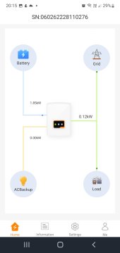
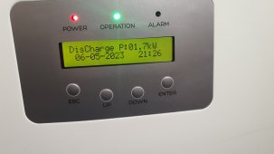
All sorted. Thanks to Daly support. I got a bms update and now my Daly and Solis work togheter ?. User defined battery and bms set for victron energy can protocol. Happy days!
 

Attachments

  • 20230506_213125.jpg
    20230506_213125.jpg
    358.7 KB · Views: 13
  • 20230506_212602.jpg
    20230506_212602.jpg
    214.6 KB · Views: 15
  • 20230506_211943.jpg
    20230506_211943.jpg
    137.8 KB · Views: 14
Just a quickie @sijones2010 - re wifi/OTA updates; is the .elf file that's the compiled binary output? (Still using the Arduino IDE here atm, so I get an output something like: vedirect.ino.elf )
 
Just a quickie @sijones2010 - re wifi/OTA updates; is the .elf file that's the compiled binary output? (Still using the Arduino IDE here atm, so I get an output something like: vedirect.ino.elf )
No, it's the ".bin" file.

Arduino conveniently hides the file in the depth of your drive, so you find it here...

C:\Users\YOURUSERNAME\AppData\Local\Temp\arduino_build_123456\VE.Direct2MQTT.ino.bin

where the items in bold will depend on your username, the project name and whatever random 6 digit number Arduino thinks of.
Fab - thanks SeaGal; found it here (running Linux):
/tmp/arduino-sketch-1ED67AF5FD866C6B3CE6ED8D1F47F250/vedirect.ino.bin

...interestingly, there's another file called:
/tmp/arduino-sketch-1ED67AF5FD866C6B3CE6ED8D1F47F250/vedirect.ino.partitions.bin

(but I'll use the first one to do the OTA flashing)
Successfully flashed - waited 'til after sunset to minimise any impact (lots of cooking done here via the battery today!)
 
Alrighty - I upped the max charge current to 62A from within config.h, but it's still capped out at around 50/51A for some reason, ever after reflashing.... & I've set the values to 62A for the custom battery setup I'm using with the Solis inverter (3.6kW H 48 blah model). Any ideas what might be happening?

(NOTE: For context, I'd originally set the max charge/discharge current to 50A, because subsequent to completing my DIY battery, I found out that the circuit breakers I've put in line with the system, are somewhat rubbish. They're rated at 200A, but it turns out that this is completly misleading, due to the poor build quality of the components, leading to them breaking at much lower currents. Fun and games. This "upgrade" to 62A is because I was getting a bit brassed off that I was missing a few kWh per day, simply because the Solis was only providing a max of 2.7kW, when charging the battery instead of 3kW, which is what it'll do on the 3.6kW hybrid model).

1684155905183.png
 

Attachments

  • 1684155789961.png
    1684155789961.png
    236.9 KB · Views: 5
Back
Top