diy solar

diy solar

DIY Battery via Smart shunt to inverter integration (Solis etc)

This "upgrade" to 62A is because I was getting a bit brassed off that I was missing a few kWh per day, simply because the Solis was only providing a max of 2.7kW, when charging the battery instead of 3kW, which is what it'll do on the 3.6kW hybrid model).
Interesting - have you definitely changed the Solis setting for charge and not discharge?

The 3.6 blah model can only discharge from battery at max 3000W (and a bit less if battery pack voltage is lower). But it can charge at 62.5A, which is more like 3.6kW. ??

My peak charge rate is consistently around 3600W - 3700W, which will obviously depend on cell voltage. Looking at the detail of one of those peaks - it happened at 53.4V pack voltage, so assuming the charge voltage is a bit higher than the cell pack, due to voltage drop over the cables is roughly consistent with the 62.5A that the 3.6kW Solis is rated to charge at (... in fact, probably a bit higher).

So, although my build is heavily modified, there's nothing wrong with Simon's code
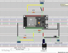
 ;) - I'd check your Solis settings and/or put some logging on to see what charge rate is being requested from the ESP32 code to the Solis.
 
the solis rai 3k asks me all the time conect can, that's I have it configured for acid batteries, but the charge its slow and i think i will need this
I realised after using Lead Acid profile for my LFP batteries for a while, that the Ah size setting throttles/limits charge and discharge current lower than the settings you manually put in.
Just set it to max (500ah) and then set your max charge and discharge amps according to your packs capability.
 

sijones2010 you did great job​

For someone like me that just starting could you please write what hardware do we need to buy inn order to built this?
-Victron smart shunt
- 60v to 5v transformer
- what else guys? any links?
Thank you
 

sijones2010 you did great job​

For someone like me that just starting could you please write what hardware do we need to buy inn order to built this?
-Victron smart shunt
- 60v to 5v transformer
- what else guys? any links?
Thank you
All the details are on @sijones2010 github page, including pics where you can see the 60v to 5v buck converter etc.
 
@sijones2010 , @SeaGal
I cant find the wire diagram, could you upload one?
The only that I can see it is the one below.

Thank you


Attachments

  • esp32.gif
    esp32.gif
    163.4 KB · Views: 97
  • 20220806_205858.jpg
    20220806_205858.jpg
    1 MB · Views: 29
Can you post the wire diagram ?
Thank you
Maybe this will be helpful, I haven't received my parts yet so can't confirm if that's correct way
 

Attachments

  • Screenshot_2023-10-05-17-30-49-05_f9ee0578fe1cc94de7482bd41accb329.jpg
    Screenshot_2023-10-05-17-30-49-05_f9ee0578fe1cc94de7482bd41accb329.jpg
    400.1 KB · Views: 31
The CAN adapter is a SPI device, you wire it as per the SPI instructions for your board. The only pin that the programmer can control is the CS (Chip Select) which i used GPIO2.
 
The pylontech protocol full enabled doesn't seem to work on my inverter anymore since it had a firmware update from Solis, turn the protocol off in the code, and use user-defined on the inverter works fine.
 
Wiring diagram, but note the CS pin is GPIO2 in the code, change in the config.h the line
#define CAN_CS_PIN 2 // CAN CS PIN
if you want to use GPIO5 instead.

maxresdefault.jpg
 
The data from the victron is done via push, the esp32 has to receive this in real time, any delay and the data is lost. This data is sent every second, so the code uses a task (thread) that has the highest priority to handle this receiving of data.
In fact the data should go to a hardware UART, that buffers the input, so the reading task is not that critical
The serial output ha a very weak +5V pull-up, which is easily clamped to 3,3v by the ESP. You don't need a voltage divisor.
 
In fact the data should go to a hardware UART, that buffers the input, so the reading task is not that critical

FYI... This is what Simon / Ralf's code already does in CANBus.h...

/*
This task will collect the data from Serial1 and place them in a block buffer
The task is independant from the main task so it should not loose data because
of MQTT reconnects or other time consuming duties in the main task
*/
void serialTask(void * pointer) {
VEDirect *ve = (VEDirect *) pointer;
String data;
startVEDirectSerial();
while ( true ) {
if ( Serial1.available()) {

i.e. using Serial1 hardware UART of the ESP32
 
This task will collect the data from Serial1 and place them in a block buffer
The task is independant from the main task so it should not loose data because
of MQTT reconnects or other time consuming duties in the main task
Doing in software, what a simple instruction does in hardware:
Code:
Serial1.setRxBufferSize(1024);

Largely enough to buffer a full second of VE message...
 
Back
Top