zanydroid
Solar Wizard
Real time status info, alarms, etc. at least, and communication between rectifiers.
Cool. What is the rectifier to rectifier communications for? Things like parallel operation?


Real time status info, alarms, etc. at least, and communication between rectifiers.
Cool. What is the rectifier to rectifier communications for? Things like parallel operation?

Emerson/Vertiv R48-series CAN programming?
Currently I'm really into getting my hands on an R48-1000e3. Highly compact and even smaller than an Eltek Flatpack S. Unfortunately I wasn't able to find somebody that's willing to share the CAN protocol with me.. I read through the Eltek thread and I wish we can start something similar for...endless-sphere.com
That should be helpful.

That's good to know, I'll probably give that seller a go since I just want a set voltage and to forget about it. I'd prefer something a little over 3kw but that seems to be the popular PSU power, at least within one unit, and curious to see the actual AC current draw from 240v.Ok, one of them arrived (the one I ordered from that Aliexpress seller). I've not tested it extensively, but it seems to work fine. Voltage output is correct as per the selected one on the store. I'll hook it up to a battery soon-ish, and start playing with the CAN interface.

 github.com
Are you able the charge charge power through CANBus commands (most easily through constant current setting)?Ok, so most of what is written in this post is correct (except for a calculation error):
Emerson/Vertiv R48-series CAN programming?
Currently I'm really into getting my hands on an R48-1000e3. Highly compact and even smaller than an Eltek Flatpack S. Unfortunately I wasn't able to find somebody that's willing to share the CAN protocol with me.. I read through the Eltek thread and I wish we can start something similar for...
To convert floats to hex, use this:
The pin-out on the connector:
View attachment 144246
I use something like this computer side:
DSD TECH USB zu CAN Bus Adapter basierend auf Open Hardware Canable : Amazon.de: Computer & Zubehör
DSD TECH USB zu CAN Bus Adapter basierend auf Open Hardware Canable : Amazon.de: Computer & Zubehörwww.amazon.de
Software I use:

GitHub - HubertD/cangaroo: open source can bus analyzer software
open source can bus analyzer software. Contribute to HubertD/cangaroo development by creating an account on GitHub.
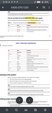
Wow! Thank you. Contacted a seller on ebay to inquire about output pinout. At over 90 years MTBF they seem like a solid option. 2 in parallel would work nicely with my smaller inverter generator.Another potential item if you are 120v only would be a EPS1500 (ICX6400-EPS1500). The put out 12v and 54v. I picked one up to test with the rackmount switches I have ,they run ~30bucks on ebay and should in theory do up to 20A of 54V which could make a nice budget DIY option for smaller gensets, with a bonus of running 12v accessories (lights, modem) directly.
The connectors are standard 20 pin ATX but theres some level of sense before output is enabled. It LOOKS like the 12v and 54v outputs are also fully isolated.
I've got a partial pinout. I have NOT tried putting the 3 outputs of a single unit in parallel (but since they are isolated it feels like it should work). I still don't have a way to enable output without the switch it powers, but I also have not opened up a unit. Whichever of us finds answers should post to the threadWow! Thank you. Contacted a seller on ebay to inquire about output pinout. At over 90 years MTBF they seem like a solid option. 2 in parallel would work nicely with my smaller inverter generator.
")
Found a detailed manual here https://fccid.io/ANATEL/01157-12-05661/Manual/8231D74B-C407-4FD2-B03C-9B749F084855/PDFWow! Thank you. Contacted a seller on ebay to inquire about output pinout. At over 90 years MTBF they seem like a solid option. 2 in parallel would work nicely with my smaller inverter generator.
Are you able the charge charge power through CANBus commands (most easily through constant current setting)?
Thanks. So a unit with 50A max charge rate corresponding to ‘121%’ would have ‘100%’ charge current of 41.3A and minimum (‘10%’) charge current of 4.13A?You can limit the output current, so yes. The output current is set in percent to the rated value of the rectifier from 10% to 121%.
These settings (voltage and current) can either be permanent, or while the command is repeated in a temporary fashion. That is, you can send a command, it will keep the settings of that command while you keep sending that command every couple of seconds or so. When you stop sending it, the original setting will be used after 30 seconds.
Oh looks like it is auto ranging up to 240v, I was wrong.Found a detailed manual here https://fccid.io/ANATEL/01157-12-05661/Manual/8231D74B-C407-4FD2-B03C-9B749F084855/PDF
with info on the pinout.
Do you know if the minimum increment above 10% is +1% or is it greater than that?
If I’m correct about ‘10%’ being 4.13A / 238W of charging power, control at the level of 1% / 0.413A / 23.8W is more than sufficient to track and limit export. 0.5% / 12W control is icing on the cake.As far as I have tested, it accepts floating points just like the voltage. You could set 10.5% for example.
I will try to make some test set-up to get more details...
It’s a bit of a pity the minimum charge power can’t be dropped below 10% - is there a CANBus command to turn the charger off of put it in standby so charge current is 0A?
Good point - thanks.You can just lower the voltage, so it's like a 'float' mode.
github.com
I got steered back to this thread by your pointer from the other new thread but thought this would be the better place to reply:Some Python code for those who want to play along:

GitHub - PurpleAlien/R48_Rectifier: CAN control of an Emerson/Vertiv R48 Rectifier
CAN control of an Emerson/Vertiv R48 Rectifier. Contribute to PurpleAlien/R48_Rectifier development by creating an account on GitHub.
- Chargeverter can be used to maintain a battery overnight at just above empty (~10%SOC or ~20% SOC) by setting voltage limits appropriately - can one of these rectifiers have voltage limits set to maintain a 48V LiFePO4 battery no lower than 49.6VDC, for example?
-we‘VE already discussed about the possibility of controlling charge current to absorb excess solar export but in this case, charge voltage would need to be increased as well.
So MODBUS control would allow voltage levels to be increased closer to 57.6VDC and then charge current to be controlled to absorb excess AC export in a ‘Daytime Mode’ before switching back to lower voltage levels for a ‘Nighttime Mode’ acting as a battery keeper?
Apologies for typing MODBUS where I meant to type CANBUS.Yes - see the code on how to set the voltage through CAN. Minimum voltage is 41V.
Max voltage on this one is 58.5V, slightly over 3.65V per cell for a 16s.
CAN, not MODBUS. But yes, you can set the voltage, and then set the max output current as a percentage of the capabilities between 10% - 121% (rated current in the datasheet = 121%), and you can limit the AC input as well, giving the possibility to reduce the overall power of the rectifier. There is a function to control voltage, current, AC limit, etc. in the Python code. All you need to do is figure out what algorithm you want based on current solar generation, etc. and you can control the rectifier to do whatever you need it to.