diy solar

diy solar

DIY "DC Coupled Multimode System" and home efficiency upgrades.

rebelrider.mike

New Member
Joined
Sep 10, 2021
Messages
32
Location
Washington, US
I live in a 1941 cinder block house. Its all-electric; no natural gas hookup.
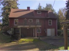
Back.jpg
My energy usage varies from 800-5,000kWh per month depending on the time of year.

I've decided to "burn the candle at both ends" and work on increasing my house's efficiency as well as trying to be less dependent on the grid. I've been working on the efficiency side for many years, and have made some progress:
  • 19 single pane windows have been replaced with modern double pane windows.
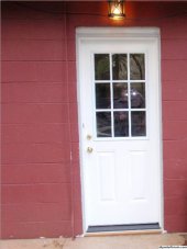
  • Kitchen exterior door was made of a single sheet of plywood, and some framing, the window was a single pane sheet of plastic, and water leaked into the basement whenever it rained. Well, that's been replaced with a modern insulated door with a double pane window. Also, the door frame was replaced. No more leaks!
  • P5020003a.jpg
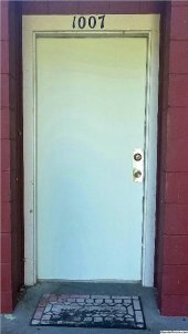
  • The front exterior door is very old and was in need of repairs. Rather than replace it, I took it down and refurbished it. Many layers of old paint was removed, and damaged areas were replaced with new wood. The plan is to improve the door frame too, and add a storm door.20210707_045414a.jpg20210707_045443a.jpg
There's plenty of other things to do to help the house's efficiency. There's lots of insulating to do. The attic has no ventilation. The exterior door in the basement... well, the whole section of wall in that area needs to be replaced. I've just gotten a couple bids to replace my electric furnace with a heat pump. I'm also looking into a heat pump water heater. Those are the really big impact things I can do.

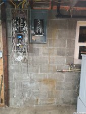
At the same time, I've been researching inverters, PV systems, and batteries for quite a while. One thing I'm realizing is that I really need a sub panel. As I've been upgrading my house electrical, code has required me to add more breakers to my already crowded main panel. Adding a sub panel will allow me to have an "optional loads" panel separate from the main panel, and also make room for future circuits on the main panel. I've been working on clearing a space for my future "power wall".
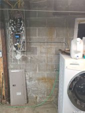
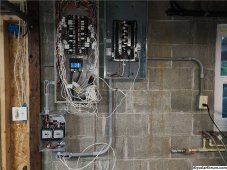
20230729_213643.jpg
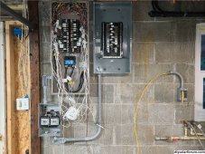
I also got one of those Vue energy monitors to help me decide which circuits to move to the sub panel. That's what all the white junk hanging out of the panel is.

The first real decision I had to make was whether or not to comply with NEC. My state uses the 2020 cycle. It took a long time, but ultimately I decided to comply and get inspections. This will make things more difficult and expensive in the short term, but I think the long term benefits will be worth it. This means that not only have I needed to dive into how all this solar/battery/inverter stuff works, but I've also had to dive into the NEC, and attempt to decode it. So this thread is going to have a lot of NEC terminology mixed in.

The next decision was what kind of system do I want? I found lots of different ways to do things. Each way is the right way for someone. For me, I chose what the NEC calls a DC coupled multimode system. DC coupled as in a hybrid inverter that can use both solar and battery. Multimode as in the inverter can operate in both grid-interactive mode and island mode. I chose this because it fits with my priorities:
  • Using less electricity from the grid.
  • Having some electricity available when the grid is down.
  • Being able to cope with long-term power outages if such a thing happens.
  • Having a positive impact on the environment would be great. Not sure I'll actually achieve that though.
Things that for me are not a priority:
  • Becoming completely independent from the grid.
  • Powering my whole house during a grid outage.
  • Trading dependence on the grid for dependence on a generator or natural gas.
  • Reluctantly, saving lots of money. (I'll get into this later.)
That's probably enough for one post. Hopefully, I'll be back with many more reports on progress.
 
Washington State ?
You need to run the numbers in a PV calculator and see what you need and can get from your desired panels location, roof or ground mount.
Also what is your biggest consumer of power, hight of summer and hight of winter.
Heat pump HVAC will help some and a hybrid hwt will help a lot....if it can heat the water in the winter from hybrid only, otherwise it will drop back to the resistive elements.
Dryers are bastards, fgb resistance load and motor both starting at the same time, heat pump models are starting to gain traction.
Any other nasty motor loads like well pumps ?

You are totally going about it the right way ?
 
Thanks!
Yeah, Washington State.
I've got a ton more info to share, but didn't want to overload the first post. I'll get into all that stuff soon. :)
 
DIY or professional install? For some, professional is the way to go. You don't have to spend hours of research. It gets done relatively quickly. It's almost certain to pass inspection. You get incentives if they are available in your area.

For me, DIY is the way to go. I enjoy learning about all this stuff. I want to be able to maintain and repair my own system. I can't afford to have it all done at once, even with incentives. One thing that almost broke the project is finding out that I can't build my own battery. I've been a battery nerd for years, and was really looking forward to designing and building a battery big enough to power a whole house. Unfortunately, 2020NEC now requires the whole battery to be listed. So I have no choice but to buy a professionally made battery. I'm mostly over it now.

Being able to spread the project out over time is very beneficial to me. However, I'd like to get it done by the beginning of 2026, as that is about when Washington will adopt the next code cycle. (We adopt every other cycle, so we're skipping 2023.) Who knows what new restrictions the NEC will come up with? Gotta get this done while I still can. At least, that's what it feels like.

So I've divided things up into three phases:
  • Install the sub panel, transfer switch, and generator. Move circuits to the sub panel that I designate "optional loads" for the future solar/battery system.
  • Install the battery and inverter. Also, I want a way to bypass the inverter and run the sub panel directly from the main panel in case some issue were to require me to take the inverter offline.
  • Install the solar array. This will require fixing up a deck and building a pergola for it. Probably the most labor intensive part of the whole project.
I've got the sub panel mounted to the wall, but it's not energized yet.
20230804_211713.jpg
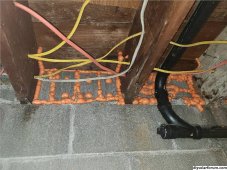
I did quite a lot of prep work before this could happen. It's not common for this area to be open and available to get cleaned up. So I did a lot of cleaning. In addition, one of my ongoing projects is to add insulation to areas of the house that lose a lot of heat in the winter. The spaces between the joists are some of these areas. I took the opportunity to clean out and seal them up with expansion foam. Then added some rigid foam I had left over from another project, and sealed that up too.
20230730_213423.jpg
I definitely wanted to get this done before adding a bunch of wires to the sub panel. You can see how they're in the way above the main panel. I'll do that space once I've moved most of those wires over to the sub panel.
20230804_211713a.jpg
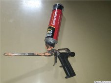
Getting the expansion foam in these areas would be almost impossible without this tool I picked up a while back:
20230730_213440.jpg
The canisters are slightly more expensive than the regular straw ones, but totally worth it. I've had this tool for years, and it makes using expansion foam so much easier.

Getting back to theory and design, I've been collecting data from the Vue, and also my utility meter, which records data points at 15min intervals. These have been very useful in deciding what circuits to move to my optional loads panel.

I think there are two ways to go about designing a system like this. You can look at how much energy you want, and try to design something that will accommodate that. Or you can look at how much energy you can actually produce, and budget your energy accordingly. To me, the second option makes the most sense. Mostly because I'm limited as to where I can put solar panels, and what size, and how many. Its like a 4D puzzle with no picture on the box. I haven't figured it all out yet, but I have made a little progress.

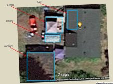
I've started by taking an arial view of my property to see what areas might be good candidates for an array:
Property.jpg
The roof isn't great. It faces west and east. It also has a dormer and chimney casting shadows throughout the day. There's a big flat carport roof. But as you can see, there's three trees casting shadows on more that half of it a lot of the day. If I were to build a pergola on the deck, that would be an ok size, and be exposed to the sun most of the day. I also have a camping trailer that I want to put solar panels on. Most of the year they'd just be sitting there doing nothing, so maybe I could add that array to the house as a sort of portable array.

So it seems the best candidate for a solar array would be to put it on a pergola roughly 15ft x 16ft. Now finding actual panels I can buy that will fit that area, and provide as much energy as possible... that's been a challenge I've been working on for a while.
 
Obvious question is do you need that chimney anymore? I am serious.
What are your ground mount possibilities?
 
Good questions. I do need the chimney. I have a working fireplace as a heat source in case of power outages. I had a liner and weather cap installed a while back, and I keep about a chord of firewood handy.

The ground on my property is shaded most of the day, by trees or structures. In the future, I may be able to add a few panels here and there, to supplement a main array. Like maybe a few panels on the roof, and if trees are ever cleared, a few panels on the carport. but for now, I think the pergola will be the most effective single spot to put an array. I would build a pergola even if I didn't want solar panels. That's always been the plan. But as long as I'm building one, may as well incorporate some solar.

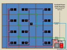
The inverter I'm looking at has 3 MPPT controllers built in. So future expansion is possible. But getting the right Voltage with a small number of panels may be a challenge. That's all way in the future though. It looks like the best fit is going to be 12 panels at 415W each. Larger than 415W and the panels will be too big to fit even 10. Smaller than 415W, and I won't be able to use all the available space. Or the Voltage will go too high.

Here's a scale drawing of the best fit panels I've found so far:
SolarArray.jpg
This will change again I'm sure. But it's sort of what I'm thinking at the moment.
 
Instead of adding a sub panel, I suggest upgrading to a Span.io pan. Especially since you will be production limited. It will help you control your power usage while on batteries.
 
Span is certainly an neat product. If I were doing a new house, or maybe completely rewiring an old one, I might get one. Especially if I wanted to run my whole house on solar. I came across a video from Matt Ferrell doing exactly that:

For what I'm doing now, it's not quite what I'm looking for. Also, the sub panel is now installed, along with the ATS:
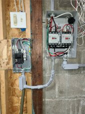
20230908_193008.jpg
A lockout system would have been cheaper, and taken up less room. But they all seem to be installed on the panel cover. So while the cover is off, there is no lockout system. That really doesn't sit well with me. Also, just to make me happy, I wanted an automatic disconnect so if there's a power outage, the main panel is instantly disconnected from everything else. Not required, but it really gives me peace of mind.

The breaker that feeds the ATS is way at the top of the panel, as far away from the main breaker as possible. (Required by code.) Since I have a panel rated for 225A, and the main breaker is 200A, I'm allowed up to 70A of back-feed breakers. I only need 50A, so that works out great.

I've been studying my energy usage recorded by the utility for the last three years. They record it in 15min intervals. It took a while, but I was able to determine that even with my house in its current state, I've never used more than 77A. I got to 77A twice in the last three years, and then only briefly. I've also been watching what my individual circuits have been doing since I installed the Vue in March this year. We've had an unusually mild summer this year, so the numbers are lower than I anticipated. But I've got a pretty good idea of which circuits will go on the sub panel.

I'm pretty sure that even using all the circuits normally, the sub panel won't see more that 30A, and most of the time will be using 20A or less. With a little energy budgeting, the whole sub panel can be powered from a 30A generator (240V) no problem. I also calculated that my most favorite circuits only, would draw less than 4A. I don't know how much math you all would be interested in seeing, so I'm just listing of the answers for now.

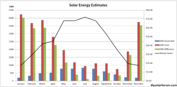
Speaking of math, I ran the numbers from those Sun Gold Power solar panels through pvwatts.nrel.gov as well as the panels I bought for the trailer array. I also reverse-engineered my electricity bill, so I could see what my kWhrs actually cost. (See, some parts of the bill stay the same regardless of how much energy I use, and so I don't include those bits in my calculations.) Together with my monthly energy usage, averaged over 3 years, I made a graph of how things might look once everything gets installed:
SolarEnergyEstimates.png
Now, this is for the house as it is today. I expect the winter energy usage to be a lot smaller once the electric furnace is replaced by a heat pump. I don't have the numbers for January-March, but in April the furnace was 53% of my total energy usage. And April wasn't all that cold. I bet as I record this next December and January, the furnace will account for around 80% of the total used.

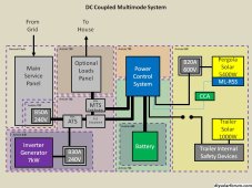
I've drawn some pictures to help me remember all the stuff I'm trying to do. They change as I learn more things, but this one shows the system as a whole, and also which parts are most affected by which NEC article:
SystemAndCode.jpg
I don't know which inverter I'm going to get yet. I need one that is listed, and has GFD and AFCI built in. That severely limits my options, but companies are coming out with new systems all the time, and it will be a while before I have to commit to buying one, so I'm not too worried. I've designed in some redundancy so I can use the main panel, sub panel, and generator independently of the inverter, battery, and solar if I ever need to. It means I have a couple extra parts in there, but I think it will be worth it if the system ever has an issue.

The first phase of the plan, adding a sub panel and generator, is going pretty well. I hope to finish by the end of the year. In the second phase, I'll add the inverter and battery by the end of 2024. And the last phase, fixing up the deck, building a pergola, and adding solar panels, hopefully by the end of 2025.
 
Span is certainly an neat product. If I were doing a new house, or maybe completely rewiring an old one, I might get one. Especially if I wanted to run my whole house on solar. I came across a video from Matt Ferrell doing exactly that:

For what I'm doing now, it's not quite what I'm looking for. Also, the sub panel is now installed, along with the ATS:
View attachment 166937
A lockout system would have been cheaper, and taken up less room. But they all seem to be installed on the panel cover. So while the cover is off, there is no lockout system. That really doesn't sit well with me. Also, just to make me happy, I wanted an automatic disconnect so if there's a power outage, the main panel is instantly disconnected from everything else. Not required, but it really gives me peace of mind.

The breaker that feeds the ATS is way at the top of the panel, as far away from the main breaker as possible. (Required by code.) Since I have a panel rated for 225A, and the main breaker is 200A, I'm allowed up to 70A of back-feed breakers. I only need 50A, so that works out great.

I've been studying my energy usage recorded by the utility for the last three years. They record it in 15min intervals. It took a while, but I was able to determine that even with my house in its current state, I've never used more than 77A. I got to 77A twice in the last three years, and then only briefly. I've also been watching what my individual circuits have been doing since I installed the Vue in March this year. We've had an unusually mild summer this year, so the numbers are lower than I anticipated. But I've got a pretty good idea of which circuits will go on the sub panel.

I'm pretty sure that even using all the circuits normally, the sub panel won't see more that 30A, and most of the time will be using 20A or less. With a little energy budgeting, the whole sub panel can be powered from a 30A generator (240V) no problem. I also calculated that my most favorite circuits only, would draw less than 4A. I don't know how much math you all would be interested in seeing, so I'm just listing of the answers for now.

Speaking of math, I ran the numbers from those Sun Gold Power solar panels through pvwatts.nrel.gov as well as the panels I bought for the trailer array. I also reverse-engineered my electricity bill, so I could see what my kWhrs actually cost. (See, some parts of the bill stay the same regardless of how much energy I use, and so I don't include those bits in my calculations.) Together with my monthly energy usage, averaged over 3 years, I made a graph of how things might look once everything gets installed:
View attachment 166990
Now, this is for the house as it is today. I expect the winter energy usage to be a lot smaller once the electric furnace is replaced by a heat pump. I don't have the numbers for January-March, but in April the furnace was 53% of my total energy usage. And April wasn't all that cold. I bet as I record this next December and January, the furnace will account for around 80% of the total used.

I've drawn some pictures to help me remember all the stuff I'm trying to do. They change as I learn more things, but this one shows the system as a whole, and also which parts are most affected by which NEC article:
View attachment 167002
I don't know which inverter I'm going to get yet. I need one that is listed, and has GFD and AFCI built in. That severely limits my options, but companies are coming out with new systems all the time, and it will be a while before I have to commit to buying one, so I'm not too worried. I've designed in some redundancy so I can use the main panel, sub panel, and generator independently of the inverter, battery, and solar if I ever need to. It means I have a couple extra parts in there, but I think it will be worth it if the system ever has an issue.

The first phase of the plan, adding a sub panel and generator, is going pretty well. I hope to finish by the end of the year. In the second phase, I'll add the inverter and battery by the end of 2024. And the last phase, fixing up the deck, building a pergola, and adding solar panels, hopefully by the end of 2025.
Nice architecture. I’ll be tracking your build.

Apologies if you already stated it and I missed it in my quick read, but what is the ‘PCS Disconnect’ (Power Control System Disconnect) - is that Grid connection to Hybrid Inverter AC Input and AC Output is connected through the Manual Transfer Switch that powers Optional Loads by either PCS power or grid power?
 
I haven't explained that part yet, but I think you have the right idea.

The MTS (manual transfer switch) will be a bypass so power from the grid can get to the sub panel without having to go through the inverter. The PCS (power control system) is what the NEC calls an inverter that does all the things besides just inverting. So from the sub panel's perspective, power can either come in from the PCS or the grid, but never both because of the MTS. I plan to use one of those switches that has two circuit breakers tied together, so it will also double as an input protection for the panel.

One thing the MTS won't do is disconnect the PCS from the grid. So if I want to shut power off to the PCS, I'd have to shut off the breaker at the main panel. But then I'd lose power to the sub panel too. So that is why I have a disconnect thrown in there too. That way if I need to, I can completely separate the PCS (and therefore also the battery and solar) from the sub panel and grid, without having to shut power off to the sub panel.

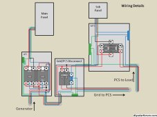
I hope that makes sense. I drew another picture showing the insides of the boxes and how they're wired:
ATSandMTSdetails.jpg
The cheapest and easiest solution I've been able to find for a disconnect switch is a 2-space load center box and a breaker. I looked all over for a 2-pole, 240VAC switch that could handle up to 50A, but the few I found were really expensive, and there was no easy way I could see to fit one in a junction box. The load center box will give me more room to work with anyway. That's good because the wires going in will need to branch off between the breaker (and on to the PCS) and the MTS (and on to the sub panel if the MTS is switched to bypass).

This setup also allows me to use the generator during a power outage either to power the sub panel directly, or through the PCS. Or I can choose to charge the battery directly from the generator using something like EG4's "Chargeverter". But hopefully, 99% of the time, the ATS, disconnect, and MTS will be sitting there doing nothing because all the other parts will be working correctly. I like having options though.

Just to mention, I did the neutral wire in blue so it would show up better in the picture. Of course in real life it will be white. Also, this is just the plan so far. These pictures change, sometimes daily, as I learn new things.
 
I haven't explained that part yet, but I think you have the right idea.

The MTS (manual transfer switch) will be a bypass so power from the grid can get to the sub panel without having to go through the inverter. The PCS (power control system) is what the NEC calls an inverter that does all the things besides just inverting. So from the sub panel's perspective, power can either come in from the PCS or the grid, but never both because of the MTS. I plan to use one of those switches that has two circuit breakers tied together, so it will also double as an input protection for the panel.

One thing the MTS won't do is disconnect the PCS from the grid. So if I want to shut power off to the PCS, I'd have to shut off the breaker at the main panel. But then I'd lose power to the sub panel too. So that is why I have a disconnect thrown in there too. That way if I need to, I can completely separate the PCS (and therefore also the battery and solar) from the sub panel and grid, without having to shut power off to the sub panel.

I hope that makes sense. I drew another picture showing the insides of the boxes and how they're wired:
View attachment 167031
The cheapest and easiest solution I've been able to find for a disconnect switch is a 2-space load center box and a breaker. I looked all over for a 2-pole, 240VAC switch that could handle up to 50A, but the few I found were really expensive, and there was no easy way I could see to fit one in a junction box. The load center box will give me more room to work with anyway. That's good because the wires going in will need to branch off between the breaker (and on to the PCS) and the MTS (and on to the sub panel if the MTS is switched to bypass).

This setup also allows me to use the generator during a power outage either to power the sub panel directly, or through the PCS. Or I can choose to charge the battery directly from the generator using something like EG4's "Chargeverter". But hopefully, 99% of the time, the ATS, disconnect, and MTS will be sitting there doing nothing because all the other parts will be working correctly. I like having options though.

Just to mention, I did the neutral wire in blue so it would show up better in the picture. Of course in real life it will be white. Also, this is just the plan so far. These pictures change, sometimes daily, as I learn new things.
This is a very capable architecture and one that I’ve considered to add backup / offgrid capability to my house.

Since your first post laid out your priorities and whole-house backup was not among them, I thought I’d share an alternative I’m leaning towards in case it holds any interest for you.

You already know about the ‘Chargeverter’ but I want to make sure you also u sets tabs how this changes the equation.

99.99% of the time you will not be servicing your PCS and so it will be able to supply your load.

When you do want to take your PCS offline you will need to be able to switch your Subpanel to grid power, but this can be done with an ATS and a breaker: main panel breaker is normally OFF to activate ATS to PCS supply and for the rare instances you want to take PCS off-line, main panel breaker switches ATS to grid.

So this architecture creates a fully-isolated Subpanel 99.99% of the time, but this raises the problem of how to supply power to the Subpanel when the battery is drained.

That’s where the Chargeverter comes in: a Chargeverter can be programmed to ‘float’ the battery at just above empty using grid energy.

The ‘cost’ of this architecture is ~5-10% overhead when the battery is being charged from grid rather than solar but the benefits are two:

1/ no possibility of spurious discharge - since the suboanel is fully isolated from the grid, there can be no spurious export to grid when a Subpanel load shuts off (less of an issue if you are getting permitted and your utility does not object to spurious export).

2/ slightly simplified wiring / components - the PCS AC input is left disconnected. The Chargeverter needs to be wired in (with an ATS for grid or generator if that is a priority), but the MTS now becomes a two-pole breaker in the subpanel controlling a second ATS that replaces both the MTS and the grid/PCS disconnect.

I’m also attracted to this alternate architecture because of reduced interdependency: you’ve got constantly-running backup power to power your subpanel from battery energy captured from solar power or from an AC charger and that Subpanel is only switched to grid power in the rare event that the PCS fails.

This alternative fully-islanded architecture obviously means being modest with the loads you put in your Subpanel to Addie they are within the capability of your PCS (no grid-assist feature) but it sounds like that is the philosophy you have used to decide what loads to take off-grid.
 
I see what you're saying. I've read about folks using the Chargeverter to draw power from the grid in order to absolutely prevent back-feed. I think something I'd lose though, is the ability to send excess power to the main panel and use it to run some of the main panel loads. This would mostly happen in the summer when solar is plentiful and power consumption is low.

Although, selling electricity back to the grid is not a priority, I'm not against it either. I need to talk with the utility to see how hard it would be to have a sell-back agreement. I don't know how to calculate it yet, but I've got a gut feeling that in the middle of the day in the summertime, I'll be producing a bit more electricity than even the whole house can use. Assuming a full battery, may as well send that unused energy out to the grid.

Related to this is return on investment. I don't have all the info I need yet to be sure, but I've started to add a few costs up to see how soon a PV system might pay for itself. Here's all the things I can think of that this project will need:
  • Generator
  • Sub Panel, and breakers
  • ATS, wiring, conduits, various parts
  • Inverter (PCS)
  • Battery, various parts
  • Chargeverter
  • MTS, PCS disconnect, various parts
  • Deck repair, pergola
  • Solar panels
  • Rapid Shutdown System
  • Wiring, conduit, breaker, various parts for solar
Now, the generator will never save me any money. In fact, I did some calculations based on the specs I got from a generator I might buy. Turns out that generating a kWh with the generator will cost 10x more than what it would cost to buy from the grid. Based on the current price of gasoline. It gets worse though. The generator is dual fuel, and can also run on propane. That would cost 40x more than buying from the grid.

I know a lady with a whole house backup propane generator. She lost power for a couple days, and the generator worked flawlessly. Later, it cost $2000 to refill the propane tank. I suppose some of that is delivery fees, but then, the issue of procuring fuel for a generator is just another good reason to store solar energy in a big battery.

Anyway, the point is there are some things I'm not going to include in my ROI calculations because I would have done them anyway. Things I'd want even if I weren't installing solar are:

  • Generator: as a convenient way to get power during an outage.
  • Sub Panel and breakers: my main panel is full, and I need this to make some room for future circuits.
  • ATS, etc..: required for the generator and sub panel.
  • Chargeverter: only needed for charging the battery during a power outage. Isn't strictly necessary.
  • Deck repair, and pergola: the deck should obviously be kept in good repair. And I want a pergola for shade.
The rest of it will be what I figure is going to be the cost of having solar. I'm including the battery, because it will be helping to spread the collected solar energy out into times when solar is less plentiful. Thus, saving money by not having to buy from the grid. The next set of numbers are very approximated, but it gives me a starting point:
  • Inverter (PCS): $5600
  • Battery: $4000
  • Solar Panels: $3000
  • RSS: $870
  • Conduit, wire, other parts: $1000 (really just a wild guess)
That total, the projected solar energy from PVWatts, the cost of energy (plus tax) from my utility bill, and my own energy usage estimates, all come together to give a very rough ROI of about 26 years. That's if I send my excess energy back to the main panel and use it to supplement the grid. If I were to have the sub panel isolated, a fair amount of energy in the summertime from the solar panels would go unused. This would increase the ROI to about 31 years. This is why, in my first post, I listed saving money as not a priority.

Of course, the ROI assumes that things are going to stay the same for the next 26-31 years. With the politicians in Washington pushing to get more electric vehicles running around, that could put a major strain on our power grid. I'm not against EVs, its just that they will be using the same power that people will be using. That could certainly lead to things like increased rates, peak usage time rates (which we don't have yet), and even rolling blackouts. How likely these things are will depend on how well the government and power company manage things. And EVs are just one variable. Even without them, demand is always increasing. Having my own source of energy means I'm doing my small part to help keep the grid from getting overloaded in the future.
 
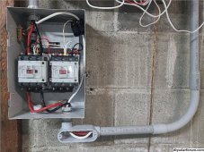
Two steps forward, one step back. The automatic transfer switch I installed needs a neutral connection to power the coil that drives the contactor. I hadn't thought of this when I decided to bypass the neutral connection and wire all neutrals together. (This is so there will always be a neutral-ground connection at the main panel.) I ordered a tap connector since I'm wanting to connect multiple 6AWG wires together, and it got delivered today. Except I didn't actually receive it.

I use a Mail and Ship company to receive all my packages so they don't get stolen. My last shipment got delivered to Burger King instead. (New courier?) So who knows where my connector ended up. Anyway, I've temporarily run a neutral from the main panel, and the ATS is now working, and therefore, so is the sub panel and cloths washer circuit:
20230915_185825.jpg
Once I actually get hold of a tap connector, I can shorten the neutral wire going to the sub panel, and trade the extra long neutral jumper for a shorter one. Just for fun, I measured the current through the neutral to see how much power the ATS uses to remain connected. 0.14A, so 16.8W. Or about 1 1/2 LED bulbs.

Keeping with the two steps forward, one step back idea, I started looking into what it would take to have a sell-back agreement with the local utility. Nothing too surprising. Though I do have to get a solar installation permit from the county, and pass some sort of inspection with them. That's in addition to passing an electrical inspection by L&I. That's a whole new set of rules that I don't know about yet. I'll have to ask them what they require. On the other hand, they may have some guidance for building a pergola. I've been told many times that a building in my county less than 200 sq. ft. doesn't need a permit. We'll see what happens.

I suppose I should stop posting a picture of the same panels every time a minor change happens. In this case though, I'm pretty excited to have power going to the sub panel finally.
 
Well, it turns out the county solar permit is pretty strait forward. Only problem is that they require anything that the solar panels will be on to be designed by an engineer. No exceptions. I'm going to think about that for a while, and hopefully come to a decision. Fortunately, I'm not planning to add the solar for a couple years, so there's no hurry.

I got my sub panel and generator inlet permit finally. Also, I found the multi tap connectors that got lost in the mail. Turns out they were delivered ok, but the package fell behind a thing and we didn't find it until I started moving stuff around. Anyway, I got the one I needed installed in the ATS, and added the neutral jumper wires for the contactor circuits. It's all working as it should:
20230927_183538.jpg

Next is to add the generator inlet parts, and move some circuits to the sub panel. That permit was not cheap though. I may have to wait until the next paycheck before buying all the parts I need.

I was reading through the NEC, and found that the 240V receptacle doesn't need GFCI. Only the receptacles that are used to power things that people are manipulating directly (like corded power tools) need GFCI. Since my receptacle will be connected to the house, GFCI isn't required. I'm still not sure about overcurrent protection. Technically, all the receptacles are supposed to have some kind of current limiting feature. Just for my own peace of mind, I'm still installing a 30A breaker between the inlet and the ATS. The breaker and the box are only an extra $40.

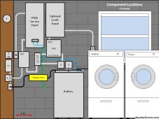
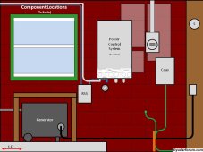
I've been working on scale drawings of where each component might go, and how things might look when all is finished. Here's what I've got so far:

Inside.
ComponentLocations.jpg

Outside.
ComponentLocationsOutside.jpg

These are works in progress, and they change often. But it's fun to see how things might look ahead of time, and it's way easier to move things around in Power Point than it is once stuff is bolted to the concrete wall. :)
 
I've been giving the county solar permit issue a lot of thought. Rather than trying to find and hire an engineer to design my solar panel mounting system. I may as well hire a solar contractor. I was hoping to avoid that, but it seems everything I want to do is illegal. Story of my life.

Anyway, I've been thinking of the pros and cons of getting a contractor vs. DIY.

Pros:
  • They'll take care of all the permits.
  • They know all the codes and requirements.
  • I'll be eligible for various incentives that I wouldn't qualify for if I do the work myself.
  • They'll know how to get me those incentives.
  • They may have better ideas as to where and how to install panels.
  • I can call on them later to repair any major incidental damage.
Cons:
  • I fear that even with incentives, their installation will cost far more than my DIY plan would.
  • I fear they will start telling me a bunch of stuff I can't do because of some company policy.
  • I wonder how much of the installation they'll let me do. Probably none.
  • They're going to want to do things their way; not my way. I hate that.
  • I may end up with a system that I can't maintain or repair myself.
  • Every contractor I've ever hired has been almost impossible to get to show up to work. I fear more of the same.
  • I won't be able to spread the cost out over time, like I'm doing now. Getting a loan is gonna hurt.
Perhaps my fears are unfounded, and I'll just get over the parts I just don't like. For now, I will continue with phase 1: sub panel and generator installation, and also do phase 2: install the house battery and inverter. Those don't need an engineer or contractor. And I'll have more time to see if a better solution presents itself.

Some good news: I've been poking around in the NEC, and I found article 250.122: Size of Equipment Grounding Conductors. I was surprised to see that it is not like I thought it was. I've always thought that the ground wire is supposed to be the same size as the current carrying conductors. But this turns out to only be true for 15 and 20 Amp circuits.

I have thought for a while that surely we don't need a 2/0 AWG ground wire for a 200A battery. But also surely, there must be a minimum size for a ground wire that only grounds the metal battery box? Turns out there is: A battery on a 200A fuse or breaker only needs a 6 AWG ground wire. This makes sense to me as my 200A main panel only has a 6 AWG copper wire going to the ground electrode. Although, technically, the wire to my ground electrode is a grounding electrode conductor, not an equipment grounding conductor. There are different rules for those.

Maybe everyone else already knows this? It's news to me. And I've seen the question asked before, and I've only ever read responses like "I don't know" and "ask your AHJ". I'm happy to know there is a specific table in the NEC I can reference.
 
professional is the way to go. You don't have to spend hours of research. It gets done relatively quickly. It's almost certain to pass inspection.
You got to really know this company or person.
“Professional “ solar is a sticky pot.

If I was to hire anyone I would grill the daylights out of them.

DIY can be done.
Just requires more research and patience but almost always less expensive but takes longer.
 
I just don't see a way around the engineering requirement. I suppose if I could find an engineer to do the design work, I can still do all the labor. That might be cheaper than a solar contractor. I have to do some research.

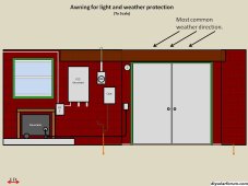
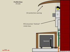
Meanwhile, I've started shopping around for some kind of protective cover for the inverter. I've been wanting a sort of awning or porch cover for the basement doors for years, so I think I'll take care of both at the same time. I found one made of polycarbonate that is 156" wide, and 38" deep. A single unit could cover both. I made some drawings (surprise!) to see how it might look:
AwningFront.jpg
AwningSide.jpg

I'll have to modify it a little to fit around the power mast, but I think that can be easily done. As an added bonus, I'll have some weather protection for the door and frame. The current ones have a lot of rot and moisture damage from weather exposure. I plan to replace them next summer. So this awning will hopefully give the new doors and frame a longer life than the current set.
 
I've been researching heat pumps for a while. I've even got a couple bids. In order to make any kind of estimate as to how much money I'll actually save, I had to make some assumptions.

First, I'm assuming that I use about 400kWh/month on electricity apart from heating and cooling.
Second, I've assumed that a heat pump will reduce the electricity I use for heating and cooling by 75%

I have no idea if these numbers are reasonable, but all the calculations are on a spreadsheet so I can change these assumptions if I need to.

After doing a ton of math, it looks like a heat pump could reduce my yearly electrical usage by 63%. If I then install solar, and set up the inverter to send excess power to the main panel, and I have an export agreement with my PUD, that could cut my yearly bill by 83%. Selling power back to the grid has increased a little as a priority.

I've had the furnace on an energy monitor since April. Once I have a year's worth of data, I'll be able to replace the first assumption with actual numbers.

Other than that, I haven't got much done as far as any installation. I did pick up a 100 lb propane tank this week. The way I have it figured, if we lose power in December (the worst month for harvesting solar energy) I'll have a small amount of energy from the solar panels, plus the house battery, plus the propane generator to keep the lights and refrigerator going. If I did my math right, 100 lbs of propane should last me a little less than a month if I'm frugal with my energy usage.

By the way, if anyone knows of any incentives or rebates or whatever for people in Washington State installing heat pumps, I'd be happy if you could share it. No way can I get a heat pump installed without a loan. And the loan payments will likely eat up my monthly home improvement budget. Which would mean no progress here for a while. The only one I know of for sure is a $1,600 rebate from PUD3, my utility. The IRS may have something, but tax laws change every year, so anything could happen there.
 
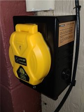
The generator inlet wiring is finished!
20231217_174452.jpg
20231217_174531.jpg
I picked this particular inlet box because it accepts the twist lock style outlet, and also a threaded collar with a gasket. Making the whole thing that much more water resistant. Now I just need a cable, and maybe a generator.

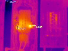
I finally got a thermal camera! Here's a couple pictures:
2023-12-17-17-48-42.jpg
Here are the main and sub panels. The two hot spots are AFCI breakers. I don't know how accurate the temperature numbers are yet. I need to find something that has a known temperature to measure. Haven't figured that out yet. Also, I've heard that bare metal sometimes looks hotter than it is because it reflects infrared light same as regular light. So on the thermal camera it's just shiny.

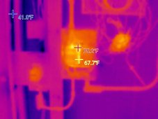
Next is the new generator shutoff box and the ATS:
2023-12-17-17-48-56.jpg
You can see the main contactor is warm, and you can sort of see behind the numbers that the generator contactor is not. It looks like it might be really hot, but its cooler than the AFCI breakers. You can also see to the right, the Emporia Vue energy monitor doing its best to look creepy.

I recently found out that Washington will be adopting the 2023 NEC early next year. I still need to install 4 more circuits before the inspection. I doubt it will happen before the 2023 NEC gets adopted. I haven't read through it yet, but I've been hearing that it's mostly changes for organization and language clarification. I hope it's true. The code sorely needs such things.
 
The generator inlet wiring is finished!
View attachment 183634
View attachment 183635
I picked this particular inlet box because it accepts the twist lock style outlet, and also a threaded collar with a gasket. Making the whole thing that much more water resistant. Now I just need a cable, and maybe a generator.

I finally got a thermal camera! Here's a couple pictures:
View attachment 183636
Here are the main and sub panels. The two hot spots are AFCI breakers. I don't know how accurate the temperature numbers are yet. I need to find something that has a known temperature to measure. Haven't figured that out yet. Also, I've heard that bare metal sometimes looks hotter than it is because it reflects infrared light same as regular light. So on the thermal camera it's just shiny.

Next is the new generator shutoff box and the ATS:
View attachment 183637
You can see the main contactor is warm, and you can sort of see behind the numbers that the generator contactor is not. It looks like it might be really hot, but its cooler than the AFCI breakers. You can also see to the right, the Emporia Vue energy monitor doing its best to look creepy.

I recently found out that Washington will be adopting the 2023 NEC early next year. I still need to install 4 more circuits before the inspection. I doubt it will happen before the 2023 NEC gets adopted. I haven't read through it yet, but I've been hearing that it's mostly changes for organization and language clarification. I hope it's true. The code sorely needs such things.
What IR camera did you get?
 
Back
Top