I've been toying with the idea of making a -very- high-powered inverter for some time now. What I've had in mind is basically a very DUMB system, using the most basic, off-the-shelf parts possible, even used ones that have gone obsolete.
The idea of it is very similar to that of huge, hundred's of kW's UPS's, except much 'dumber', allowing for adaptation
My idea is to have something so basic that it just works. IGBT blew up? no problem, I have 4 more spares, maybe replace the gate drivers and what the hell an EGS002 board is worth what, $3? Less if you buy a couple? And we're back in business. One of those fancy inverters blows up on you and you might as well buy a new one cause you'll never figure out how to fix it. This? It's basically Mad-Max ready. As long as the sun is still shining we'll have power, baby. Just make sure to keep the spares wrapped in tin foil and grounded!
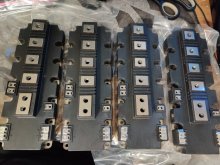
By that I mean, we have an H-Bridge driven by your off-the-shelf EGS002 board, using second hand IGBT's (most are from UPS's as well) allowing for massive currents. I recently purchased 6 TOSHIBA MG300J2YS40 Half-Bridges that can handle 300A each at 600V. These cost me $15 a piece, which is actually dumb cheap considering their specs. (and how much a similar part would cost new)
Sure, they are aged, but given the amount of design that UPS's have, I doubt they were even stressed much more than even 20% their rated specs. I understand some people's concerns with buying used parts, but in MY opinion these are a good buy.
(Source: I work with MRI's+X-rays which in many cases are connected to 250kW+ UPS's. Most of the time when they buy a new MRI they also buy a new UPS as a bundle package, the old UPS then is basically worth scrap as it's extremely expensive to uninstall, transport, then install, and most of the time the batteries are in bad condition (they never cycle them, just sit at float voltage for 10+ years), just in batteries they'd spend over $100k, so they'd rather send them to scrapyards or give them away for free. Then these ebay sellers take them apart and sell the parts. I have yet to hear of a UPS stop working or be damaged in any way besides batteries being dead.)
I don't have much experience with inverters, but I do have experience with Arduino's as well with all sorts of random circuits, both tiny and huge, and of course high-voltage.
But anyways, the basic idea is: we have a ~350VDC reservoir, this could be either some capacitors or a battery, or a combination of both. Off-the-shelf EGS002 board sends the gate signals to some higher-current totem pole drivers, which switch the gates of the IGBT's. 2 of these half bridge modules make a full 300A H-bridge. With de-rating a pair of these should EASILY be able to handle 10kW continuous and 20kW peaks all day, and even then you could parallel them and have a literally bulletproof output stage. (I know some people also dislike paralleling IGBT's but that's how they do it in the UPS's, and I trust them)
The reservoir could be a decently sized capacitor bank, (charged by a high-frequency transformer from a low-voltage 48V or so battery pack) or even better a high-voltage battery (which is what the UPS's do, they have ALL the batteries in series). This would allow you to skip a complete stage of the inverter. This is exactly how the Tesla Powerwall works.
You can then directly charge/maintain the 350vdc reservoir with solar panels very easily with a basic PWM circuit (at 350v, one of these $15 IGBT's can easily handle 100A of solar charging which is dumb overkill, but anyways.
They do sell such inverters https://www.ebay.com/itm/233314195391?ul_noapp=true but that's not my goal personally.
But yeah, sorry for the long winded post. My brain is churning a bit. I am also buying components for a high-frequency transformer like the ones you guys are going for in the DIY inverter thread, to boost 12-48v into 350v. Maybe not 10kW but a decent amount. I got a 100x50x25 ferrite core coming from Ali. It's SUPPOSEDLY Amorphous Nanocrystalline which allows for over 2x the Gauss rating of a normal ferrite core. Also 2.5Lbs of 30awg enameled wire to make some Litz wire. But I have no idea as for what I'm gonna do. I REALLY want to go directly for a ~350VDC battery pack but for now I just want to make the inverter head and a boost converter for proof of concept/emergencies. Also have 30 original HY4008W mosfets for the push-pull, which I don't really want to use all of, maybe 8 in parallel for the push-pull so 16 total?
What really draws me away from doing a low-voltage system is the beefiness and the added complexity of the components required, when one could put all their batteries in series and avoid all of it.
With a decent capacitor bank and enough solar though you could easily pump 10kW through a VERY simple H-bridge with 2 of these IGBT's and another controlling the solar into it. And then the boost circuit to maintain the voltage if there isn't enough solar or at night.
Could easily use one of those huge 40kVA+ 3 Phase 208Y isolation transformers that pop up locally for dirt cheap ($100-200), which will allow you to not only get a split phase system but also add peak power capacity as the huge transformer acts like a flywheel.
You know, the more I think about this the more it feels like I'm just thinking up a UPS except I'll be able to fix it if it ever blows up...
I know this is a long post but it's a lot of different thoughts. If you can help in any way I would very gladly appreciate it. I'm not one of those people that just comes up with an idea and forgets about it, I am invested into doing this, but like I mentioned earlier I have never designed an inverter, so any tips and guidance will go a long way. I'm currently looking to see what I could use as gate drivers for the IGBT's and what other components I may need to have a functioning 350vdc-220vac inverter.
I have begun to search for basic inverter designs using the EGS002 and looking for a suitable one to basically scale up for the IGBT's. Would this be a good starting path?
Current Parts:
6x Toshiba MG300J2YS40 600V 300A Half-Bridges
30x HY4008 80V, 200A Mosfets
5X APT2X61DC60J 600V 60A SiC Dual-Diode modules
1x 100mmx50mmx25mm ferrite core
2.5lbs of 30AWG enameled copper wire
3x EGS002 driver boards
-many little components, resistors, capacitors, diodes, that I can use to prototype.
Need:
-IGBT Gate drivers
-Push-pull driver board. I'm between the EG7500 boards and SG3525 boards. My main concern is overcurrent protection and how they would react to it. Ideally one could have the boost driver react not only to the output voltage but the current as well, that way we could have a wide input voltage like 12-48v and it would be able to adapt to it. Cause I think if I make the transformer a 2+2 primary and 65 secondary it would work perfectly for 12v let's say, but if I connected it to 48v I feel we would need a duty cycle 1/4 that of 12v's in order to avoid drawing too much current. Not sure if any pre-made board is able to do that.
The idea of it is very similar to that of huge, hundred's of kW's UPS's, except much 'dumber', allowing for adaptation
My idea is to have something so basic that it just works. IGBT blew up? no problem, I have 4 more spares, maybe replace the gate drivers and what the hell an EGS002 board is worth what, $3? Less if you buy a couple? And we're back in business. One of those fancy inverters blows up on you and you might as well buy a new one cause you'll never figure out how to fix it. This? It's basically Mad-Max ready. As long as the sun is still shining we'll have power, baby. Just make sure to keep the spares wrapped in tin foil and grounded!
By that I mean, we have an H-Bridge driven by your off-the-shelf EGS002 board, using second hand IGBT's (most are from UPS's as well) allowing for massive currents. I recently purchased 6 TOSHIBA MG300J2YS40 Half-Bridges that can handle 300A each at 600V. These cost me $15 a piece, which is actually dumb cheap considering their specs. (and how much a similar part would cost new)
Sure, they are aged, but given the amount of design that UPS's have, I doubt they were even stressed much more than even 20% their rated specs. I understand some people's concerns with buying used parts, but in MY opinion these are a good buy.
(Source: I work with MRI's+X-rays which in many cases are connected to 250kW+ UPS's. Most of the time when they buy a new MRI they also buy a new UPS as a bundle package, the old UPS then is basically worth scrap as it's extremely expensive to uninstall, transport, then install, and most of the time the batteries are in bad condition (they never cycle them, just sit at float voltage for 10+ years), just in batteries they'd spend over $100k, so they'd rather send them to scrapyards or give them away for free. Then these ebay sellers take them apart and sell the parts. I have yet to hear of a UPS stop working or be damaged in any way besides batteries being dead.)
I don't have much experience with inverters, but I do have experience with Arduino's as well with all sorts of random circuits, both tiny and huge, and of course high-voltage.
But anyways, the basic idea is: we have a ~350VDC reservoir, this could be either some capacitors or a battery, or a combination of both. Off-the-shelf EGS002 board sends the gate signals to some higher-current totem pole drivers, which switch the gates of the IGBT's. 2 of these half bridge modules make a full 300A H-bridge. With de-rating a pair of these should EASILY be able to handle 10kW continuous and 20kW peaks all day, and even then you could parallel them and have a literally bulletproof output stage. (I know some people also dislike paralleling IGBT's but that's how they do it in the UPS's, and I trust them)
The reservoir could be a decently sized capacitor bank, (charged by a high-frequency transformer from a low-voltage 48V or so battery pack) or even better a high-voltage battery (which is what the UPS's do, they have ALL the batteries in series). This would allow you to skip a complete stage of the inverter. This is exactly how the Tesla Powerwall works.
You can then directly charge/maintain the 350vdc reservoir with solar panels very easily with a basic PWM circuit (at 350v, one of these $15 IGBT's can easily handle 100A of solar charging which is dumb overkill, but anyways.
They do sell such inverters https://www.ebay.com/itm/233314195391?ul_noapp=true but that's not my goal personally.
But yeah, sorry for the long winded post. My brain is churning a bit. I am also buying components for a high-frequency transformer like the ones you guys are going for in the DIY inverter thread, to boost 12-48v into 350v. Maybe not 10kW but a decent amount. I got a 100x50x25 ferrite core coming from Ali. It's SUPPOSEDLY Amorphous Nanocrystalline which allows for over 2x the Gauss rating of a normal ferrite core. Also 2.5Lbs of 30awg enameled wire to make some Litz wire. But I have no idea as for what I'm gonna do. I REALLY want to go directly for a ~350VDC battery pack but for now I just want to make the inverter head and a boost converter for proof of concept/emergencies. Also have 30 original HY4008W mosfets for the push-pull, which I don't really want to use all of, maybe 8 in parallel for the push-pull so 16 total?
What really draws me away from doing a low-voltage system is the beefiness and the added complexity of the components required, when one could put all their batteries in series and avoid all of it.
With a decent capacitor bank and enough solar though you could easily pump 10kW through a VERY simple H-bridge with 2 of these IGBT's and another controlling the solar into it. And then the boost circuit to maintain the voltage if there isn't enough solar or at night.
Could easily use one of those huge 40kVA+ 3 Phase 208Y isolation transformers that pop up locally for dirt cheap ($100-200), which will allow you to not only get a split phase system but also add peak power capacity as the huge transformer acts like a flywheel.
You know, the more I think about this the more it feels like I'm just thinking up a UPS except I'll be able to fix it if it ever blows up...
I know this is a long post but it's a lot of different thoughts. If you can help in any way I would very gladly appreciate it. I'm not one of those people that just comes up with an idea and forgets about it, I am invested into doing this, but like I mentioned earlier I have never designed an inverter, so any tips and guidance will go a long way. I'm currently looking to see what I could use as gate drivers for the IGBT's and what other components I may need to have a functioning 350vdc-220vac inverter.
I have begun to search for basic inverter designs using the EGS002 and looking for a suitable one to basically scale up for the IGBT's. Would this be a good starting path?
Current Parts:
6x Toshiba MG300J2YS40 600V 300A Half-Bridges
30x HY4008 80V, 200A Mosfets
5X APT2X61DC60J 600V 60A SiC Dual-Diode modules
1x 100mmx50mmx25mm ferrite core
2.5lbs of 30AWG enameled copper wire
3x EGS002 driver boards
-many little components, resistors, capacitors, diodes, that I can use to prototype.
Need:
-IGBT Gate drivers
-Push-pull driver board. I'm between the EG7500 boards and SG3525 boards. My main concern is overcurrent protection and how they would react to it. Ideally one could have the boost driver react not only to the output voltage but the current as well, that way we could have a wide input voltage like 12-48v and it would be able to adapt to it. Cause I think if I make the transformer a 2+2 primary and 65 secondary it would work perfectly for 12v let's say, but if I connected it to 48v I feel we would need a duty cycle 1/4 that of 12v's in order to avoid drawing too much current. Not sure if any pre-made board is able to do that.


.jpg")
.jpg")