diy solar

diy solar

DIY Inverter

I suggested parallel-series transformer confiquration bit earlier: primaries in parallel, secondaries in series. You get perfect current sharing between transformers and mosfets. And you can possibly use 1:1 transformers that simplifies the winding and sourcing parts.
I have a LT Spice file if you are interested I will get it to you. Push-pull transformer with voltage doubler secondary - that gets you about 100v out. Two of these supplies on one board with outputs in parallel is then near 200v.
 
Last edited:
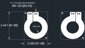
I have a guy looking at stamping this out of 0.010" low oxygen copper. He has multiple ways,including laser, of getting this done. These would slip on an ER64 planar core. This one part could be used for both the primary and secondary windings. I expect he would be happy with a 5 bucks per winding. That is a $30 transformer. I got a target of $500 for a 5kW inverter with a 10kW overload rating. Comments?
 
I have a LT Spice file if you are interested I will get it to you. Push-pull transformer with voltage doubler secondary - that gets you about 100v out. Two of these supplies on one board with outputs in parallel is then near 200v.
Sure, I’m curious what you have cooked in ltspice.
 
Once you need more than 4 layers and 1oz copper the 8 usd Cheap boards becomes 1000 usd "cheap" :(
At minimum we would need some sort of group buy. 12-layer 6oz board from pcbway.com is 1002 usd for 5 pcs and 2370 usd for 100pcs.

Maybe could use for some low-power project where 4-layer 1 oz board would be ok.

Sure, I’m curious what you have cooked in ltspice.
 
This is a push-pull with series resonant LC on the transformer output. It allows for primary fet switching at near zero current. I would like synchronous rectification on the output, but with 120v or 240v output at a few kW the output rectifiers aren't so bad. transformers are 1:1 so easier to get good coupling. Notice the open-loop output regulates fairly well with a large step in current. Inverter will probably look at dc link voltage and calculate modulation index rather than using feedback from output. I have posted a drawing of the Planar transformer windings which I think can be stamped or laser cut for a very reasonable price. Shit - will not let me upload an .asc file. Here is .txt file just open and save with .asc extension and LT should open it. If not I will post it on my website and you can grab it, One more thing - there are some clamp diodes on one of the primary fets that I was playing with. Once transformer leakage reactance is determined exact snubbers and/or clamps can be dialed in
 

Attachments

  • push-pull10.txt
    7.6 KB · Views: 8
This is a push-pull with series resonant LC on the transformer output. It allows for primary fet switching at near zero current. I would like synchronous rectification on the output, but with 120v or 240v output at a few kW the output rectifiers aren't so bad. transformers are 1:1 so easier to get good coupling. Notice the open-loop output regulates fairly well with a large step in current. Inverter will probably look at dc link voltage and calculate modulation index rather than using feedback from output. I have posted a drawing of the Planar transformer windings which I think can be stamped or laser cut for a very reasonable price. Shit - will not let me upload an .asc file. Here is .txt file just open and save with .asc extension and LT should open it. If not I will post it on my website and you can grab it, One more thing - there are some clamp diodes on one of the primary fets that I was playing with. Once transformer leakage reactance is determined exact snubbers and/or clamps can be dialed in
1uF C8 resonant capacitor has 32 Arms current. And caps C1 C2 C8 C9 each have 17Arms circulating current trough them.
What did you plan to use for caps?
I'm afraid 200uF of anything with 17A ripple current rating is expensive.
Or is the actual capacitance going to be larger and simulation uses 200uF to reach steady-state faster?
 
Thanks for reviewing
1uF C8 resonant capacitor has 32 Arms current. And caps C1 C2 C8 C9 each have 17Arms circulating current trough them.
What did you plan to use for caps?
I'm afraid 200uF of anything with 17A ripple current rating is expensive.
Or is the actual capacitance going to be larger and simulation uses 200uF to reach steady-state faster?
I would probably use SMT ceramic both places. The resonant circuit must be stable. I would tend towards running a few in parallel to spread the current around. The 200uf caps can be reduced to about 10X the resonant cap. 20uF/50v would work. There should be some larger electrolytic caps near to inverter input side to take care of a reactive load. 200uf/200v parts aren't too big. You think that plan is ok?
 
Thanks for reviewing

I would probably use SMT ceramic both places. The resonant circuit must be stable. I would tend towards running a few in parallel to spread the current around. The 200uf caps can be reduced to about 10X the resonant cap. 20uF/50v would work. There should be some larger electrolytic caps near to inverter input side to take care of a reactive load. 200uf/200v parts aren't too big. You think that plan is ok?
Sounds good. 1uF resonant caps can be probably bunch of c0g ceramics parallel, 10x 100nF parallel should be able to handle the ripple current easily? (annoyingly Murata SimSurf doesn't give ripple rating for c0g's!)

If we want to have actual 20 uF at 50v that calls probably derating to 47uF 100v due to capacitance-voltage loss with any of the high capacitance grades. Murata 4.7uF 100v X7R (KCM55LR72A475KH01) for example has abt 2.5uF capacitance left at 50v bias. Factor in rest of the fudge factors and we might get 20uF actual capacitance with 10x of those parallel. 3A ripple current per piece would be ok according to simsurf so that part is easily satisfied.

Those ceramics are going to end up surprisingly large part of the BOM. 4x10 = 40pcs 4.7uF 100V X7R caps are currently about 3 usd per piece from digikey. =120 usd for those alone.
 
Yes, I was thinking of 10 of the 0.1uF myself... and yes they are expensive. I thought I found some for about 1$. If this ever gets built the value the resonant switching adds and cost to see if it makes sense. TDK Corporation C3216C0G2A104J160AE looks like about a buck.

I didn't realize the capacitance went down that much - just more $$$. The output filter caps need to be fairly low impedance for the resonant network to dump pulses into. I don't thing an electrolytic would be good. Those Os-Con caps were nice, but probably more money than the ceramics. The output caps don't need to be NPO tho.
Resonant caps are the cheaper part and you need "only" 20pcs of them vs 40pcs output filter caps.
NP0 doesn't need voltage derating like X7R needs so 50V NP0's might be ok.
These are only something like 30 cents per piece https://www.digikey.com/en/products/detail/tdk-corporation/CGA5L2C0G1H104J160AA/2672877

If going electrolytic we would need quite a lot of space compared to MLCC but it is definitely cheaper option.
6pcs of those parallel would handle the ripple current requirement. 24 mOhm ESR so 6x parallei combo would lead to around 1.1W losses total per 6 caps. That would be only 34 usd for output caps instead of 120 usd for X7R MLCC's
Yes, those are good parts and will save some money. I just did digikey search and landed on the same parts. I used 25mm for tallest. I looked at a few switches too. Fets, SiC and an IGBT. I think the TO-247 is probably best package
 
Yes, those are good parts and will save some money. I just did digikey search and landed on the same parts. I used 25mm for tallest. I looked at a few switches too. Fets, SiC and an IGBT. I think the TO-247 is probably best package
I got the inverter schematic 1/2 done in Altium. I'm going to lay board out for 2 of these on each corner. They are fairly expensive, but should run nice. There are also some MOS fets and maybe an IGBT or two worth looking at. Of course IGT will need a diode. So maybe one hole in each corner for IGBT and diode would work too.
 

Attachments

  • SICFet.pdf
    401.7 KB · Views: 8
Back
Top