diy solar

diy solar

DIY Vendor agnostic Smart Shunt & Victron Smart Solar MPPT data logger based on ESP8266

Here a 48V Version: the VBus input gets 1/2 of the battery voltage. I will double the input value in software.
Be cautious to use a high voltage capable buck converter !
Schematic

Configuration:
Code:
//----------------------- HARDWARE OPTIONS ---------------------------------
#define AO_IS_NONE        // _NONE , _DOUBLEBATTERY , _HALFBATTERY, _PANEL, _POT
#define A0_MAX       15   // if A0 is used, define the voltage of the full range measure
#define D0_IS_NONE        // _NONE , _RELAY1
#define D5_IS_NONE        // _NONE , _RELAY2
#define D6_IS_NONE        // _NONE , _RELAY3, _VE_BLOCK, _VE_START_STOP
#define D7_IS_NONE        // _NONE , _RELAY4; _VICTRON
#define OLED_IS_64x48     // _NONE , _64x48 , _128x64
#define OLED_IS_REVERSED  // _IS_NORMAL, _IS_REVERSED To turn the display 180° if required
#define INA_IS_226        // _NONE , _226
#define INA_VBUS_IS_HALF  // _FULL _HALF   (when high voltage schematic is used)
 
Schematic (as far as a schematic is required)
View attachment 180278
this is very helpful and a great project - the photo shows 4 wires from victron direct port - white as shown in schematic but also yellow, black and red. Could you please explain those and pinouts? I assume black is a necessary ground? thanks
 
Last edited:
this is very helpful and a great project - the photo shows 4 wires from victron direct port - white as shown in schematic but also yellow, black and red. Could you please explain those? thanks
yellow would have been Victron data input. We don't use it.
Black is Ground ~ Battery minus
Red is +5V but it is too weak (20mA max) to power an ES8266: we have to make our own +5v from the Battery plus over a buck converter.
 
Schematic (as far as a schematic is required)
View attachment 180278
good white TX & black ground - could you please give some guidance on a minimal "Hello World equivalent" data logger - ie just able to handle case V? I can't quite figure out which modules are need - c_setup is clear and config.h - what is needed in void loop() besides menu & serial? thanks (fyi I've done several arduino project so know the basics)
 
Last edited:
good white TX & black ground - could you please give some guidance on a minimal "Hello World equivalent" data logger - ie just able to handle case V? I can't quite figure out which modules are need - c_setup is clear and config.h - what is needed in void loop() besides menu & serial? thanks (fyi I've done several arduino project so know the basics)
Just connect TX. The ground comes from the battery.
To compile, don't worry, just use all .ino and .h files.
Just modify credentials.h and Config.h to adjust to your needs. Put _NONE to what you don't use (the compiler will ignore what is not used):
Code:
//----------------------- HARDWARE OPTIONS ---------------------------------
#define AO_IS_NONE        // _NONE , _DOUBLEBATTERY , _HALFBATTERY, _PANEL, _POT
#define A0_MAX       15   // if A0 is used, define the voltage of the full range measure
#define D0_IS_NONE        // _NONE , _RELAY1
#define D5_IS_NONE        // _NONE , _RELAY2
#define D6_IS_NONE        // _NONE , _RELAY3, _VE_BLOCK, _VE_START_STOP
#define D7_IS_VICTRON        // _NONE , _RELAY4; _VICTRON
#define OLED_IS_NONE     // _NONE , _64x48 , _128x64
#define OLED_IS_NORMAL  // _IS_NORMAL, _IS_REVERSED To turn the display 180° if required
#define INA_IS_NONE        // _NONE , _226
#define INA_VBUS_IS_HALF  // _FULL _HALF   (when high voltage schematic is used)
#include "MPPT_75_15.h" // Put here your used Victron module if D7_IS_VICTRON
//#include "SHUNT_10A_75mV.h" // Put here your Shunt module if INA_IS_""&
#include "LiFePo_13V_100Ah.h" //Put here the type of Battery module used

//----------------------- SOFTWARE OPTIONS ---------------------------------
#define WEATHER_IS_NONE     // _NONE , _OWM , _BME680       // (Source of the Weather Information)
#define DASHBRD_IS_NONE    // _NONE , _THINGER          // (Internet Dashboard)
#define TERM_IS_TELNET     // _NONE , _TELNET, _SERIAL , _SOFTSER // defines where do Menus and Reports occur: _SERIAL and D7_IS_VICTRON are mutually exclusive )
#define UDP_IS_NONE        // _NONE , _SEND , _RECEIVE  // (UDP Inter-ESP Communication)
#define COM_IS_NONE        // _NONE , _HOURLY           // Periodical reports to computer
#define ESP_UDP_ADDR   "192.168.188.64"                  // (IP of the receiving ESP)
#define ESP_UDP_PORT    4200  // (Port used to send/receive Values to other ESP)
#define COM_UDP_ADDR   "192.168.188.1"                  // (IP of the receiving computer for night reports)
#define COM_UDP_PORT    4200                            // (Port used to send/receive Values to other computer)
#define DEVICE_NAME    "ESP_VICTRON"                         // Name of the device used as Hostname and at Thinger.io
#define DEVICE_NUMBER   0                               // 0 if no ESP32 supervisor, else 1..4

//--------------------------- ESP SETUP -------------------------------------
#define WIFI_REPEAT          500
#define WIFI_MAXTRIES        20
#define WIFI_POWER           7.5

//----------------------DO NOT EDIT until you know what you do -------------
#define SERIAL_SPEED          19200
#define LDR        A0
#define BUTTON     D2    // GPIO04
#define STDLED     D4    // GPIO02
#define REDLED     D8    // GPIO15 (used as TX after Serial.swap,n/a on WemosD1)
#define GRNLED     D6    // GPIO12
#define BLULED     D7    // GPIO13 (used as RX after Serial.swap)
#define RELAY1     D0    // GPIO16 Relay or FET control 1
#define RELAY2     D5    // GPIO14 Relay or FET control 2
You must also copy modules corresponding to your Victron type and Battery configuration (here MPPT_75_15.h and LiFePo_13V_100Ah.h)
in your libraries folder.

If you are usure, tell me what Victron Model you have and the characteristics of your battery.
Regards
 
Just connect TX. The ground comes from the battery.
To compile, don't worry, just use all .ino and .h files.
Just modify credentials.h and Config.h to adjust to your needs. Put _NONE to what you don't use (the compiler will ignore what is not used):
Code:
//----------------------- HARDWARE OPTIONS ---------------------------------
#define AO_IS_NONE        // _NONE , _DOUBLEBATTERY , _HALFBATTERY, _PANEL, _POT
#define A0_MAX       15   // if A0 is used, define the voltage of the full range measure
#define D0_IS_NONE        // _NONE , _RELAY1
#define D5_IS_NONE        // _NONE , _RELAY2
#define D6_IS_NONE        // _NONE , _RELAY3, _VE_BLOCK, _VE_START_STOP
#define D7_IS_VICTRON        // _NONE , _RELAY4; _VICTRON
#define OLED_IS_NONE     // _NONE , _64x48 , _128x64
#define OLED_IS_NORMAL  // _IS_NORMAL, _IS_REVERSED To turn the display 180° if required
#define INA_IS_NONE        // _NONE , _226
#define INA_VBUS_IS_HALF  // _FULL _HALF   (when high voltage schematic is used)
#include "MPPT_75_15.h" // Put here your used Victron module if D7_IS_VICTRON
//#include "SHUNT_10A_75mV.h" // Put here your Shunt module if INA_IS_""&
#include "LiFePo_13V_100Ah.h" //Put here the type of Battery module used

//----------------------- SOFTWARE OPTIONS ---------------------------------
#define WEATHER_IS_NONE     // _NONE , _OWM , _BME680       // (Source of the Weather Information)
#define DASHBRD_IS_NONE    // _NONE , _THINGER          // (Internet Dashboard)
#define TERM_IS_TELNET     // _NONE , _TELNET, _SERIAL , _SOFTSER // defines where do Menus and Reports occur: _SERIAL and D7_IS_VICTRON are mutually exclusive )
#define UDP_IS_NONE        // _NONE , _SEND , _RECEIVE  // (UDP Inter-ESP Communication)
#define COM_IS_NONE        // _NONE , _HOURLY           // Periodical reports to computer
#define ESP_UDP_ADDR   "192.168.188.64"                  // (IP of the receiving ESP)
#define ESP_UDP_PORT    4200  // (Port used to send/receive Values to other ESP)
#define COM_UDP_ADDR   "192.168.188.1"                  // (IP of the receiving computer for night reports)
#define COM_UDP_PORT    4200                            // (Port used to send/receive Values to other computer)
#define DEVICE_NAME    "ESP_VICTRON"                         // Name of the device used as Hostname and at Thinger.io
#define DEVICE_NUMBER   0                               // 0 if no ESP32 supervisor, else 1..4

//--------------------------- ESP SETUP -------------------------------------
#define WIFI_REPEAT          500
#define WIFI_MAXTRIES        20
#define WIFI_POWER           7.5

//----------------------DO NOT EDIT until you know what you do -------------
#define SERIAL_SPEED          19200
#define LDR        A0
#define BUTTON     D2    // GPIO04
#define STDLED     D4    // GPIO02
#define REDLED     D8    // GPIO15 (used as TX after Serial.swap,n/a on WemosD1)
#define GRNLED     D6    // GPIO12
#define BLULED     D7    // GPIO13 (used as RX after Serial.swap)
#define RELAY1     D0    // GPIO16 Relay or FET control 1
#define RELAY2     D5    // GPIO14 Relay or FET control 2
You must also copy modules corresponding to your Victron type and Battery configuration (here MPPT_75_15.h and LiFePo_13V_100Ah.h)
in your libraries folder.

If you are usure, tell me what Victron Model you have and the characteristics of your battery.
Regards
Thanks very much, I'll work through that and come back if I get stuck...
 
a few follow up questions:

1) let me make sure I have basic structure correct in main .ino file

paste a_libs.Vars.ino that has the include statements

paste c_Setup.ino ie void setup()

paste s_Scheduler.ino ie void setup()

paste all the other ino files

getting many redefinition compile errors so must have something basic wrong

2) My setup is a ESP32 connected via its usb to my computer for development so I believe I need TERM set to SERIAL but I see a note that D7 can't at the same time be set to Victron??

3) I can't find an example battery .h file to edit - in my case it will be LiFePo_26V_200Ah.h" -created a null file with that name but perhaps content not necessary?

4) I'm using a Victron 100/50 so I just renamed the 100_30 file - but didn't see any values that needed to be changed.


if you prefer we can continue by email - cameron@cameronfraser.ca

thanks again
 
a few follow up questions:
1) let me make sure I have basic structure correct in main .ino file
paste a_libs.Vars.ino that has the include statements
paste c_Setup.ino ie void setup()
...
Look at my instructions below on how to download the code from GitHub.
2) My setup is a ESP32 connected via its usb to my computer for development so I believe I need TERM set to SERIAL but I see a note that D7 can't at the same time be set to Victron??
You ought to use TERM set to TELNET. It is a much better way (wireless i.e. no surge risk) to connect.
An ESP32 can basically open a second serial to D7 , but i did not test it yet.
For an ESP8266, which I recommend, it is still the far best option.
3) I can't find an example battery .h file to edit - in my case it will be LiFePo_26V_200Ah.h" -created a null file with that name but perhaps content not necessary?
I have removed that line. Currently I don't need it. Later, when I have a working algorithm to compute the SOC I may need it.
4) I'm using a Victron 100/50 so I just renamed the 100_30 file - but didn't see any values that needed to be changed.
Normally that should work. I had no opportunity to test, let me know.
if you prefer we can continue by email - cameron@cameronfraser.ca
I prefer putting the instructions here which can be useful to others.

**************
You don't need to paste each file form GitHub, if you have installed git.
The regular way to do it is to do it with the git clone command
Code:
git clone rin67630/Victron_VE_on_Steroids [your target folder]

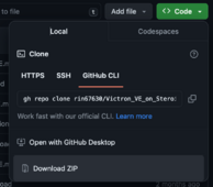
If you don't want to install something to your computer, you can download a .zip file containing all files you need.
1708245190805.png
Unzip that file and copy the Software folder to a folder named ESP8266_Victron_on_Steroids in your usual Arduino IDE sketch location.
Copy the Config_files in the libraries folder of your Arduino IDE.
Then begin to personalize the Credentials.h and the Config.h

N.B. the Software ESP32 should work too, but is two months behind the ESP8266 development.
I will catch-up that week

Regards.
 
Last edited:
1) I have already downloaded zip files for 8266 and 32. Paste is perhaps not the best word - I'm trying to understand how to add the .ino modules to the main file "ESP8266_Victron_on_Steroids.ino" which is just a comment header.
c_setup.ino is clear ie the Arduino required void setup()
s_Scheduler.ino is clear ie the required void loop()

a_Libs_Vars.ino is placed at top of file since it has the include config files

so do the rest of the ino files go after s_Scheduler.ino?

ie
ESP8266_Victron_on_Steroids.ino
add code from a_Libs_Vars.ino
add code from c_setup.ino
add code from s_Scheduler.ino
add code from rest of .ino files

2) I'll switch to a ESP8266 development board to have as close a setup as yours to start with. I'll use the USB on the 8266 deveopment board to download from IDE, D7 to victron and telnet for menu access.
To use WIFI the zip files are missing a template for the Credentials file - (without the personal info of course)?

thanks for your patience
 
1) I have already downloaded zip files for 8266 and 32. Paste is perhaps not the best word - I'm trying to understand how to add the .ino modules to the main file "ESP8266_Victron_on_Steroids.ino" which is just a comment header.
It is not that complicated.
Just copy the content of the Software folder in a folder named ESP8266_Victron_on_Steroids, which is placed at the sketch location that you have configured to hold your Arduino IDE sketches.
You find that folder at the beginning of Settings from your Arduino IDE.
You would then place your files in [that folder]/ESP8266_Victron_on_Steroids.
Then it will be listed in Files -> Sketchbook and you have all files in place.
2) I'll switch to a ESP8266 development board to have as close a setup as yours to start with. I'll use the USB on the 8266 development board to download from IDE, D7 to victron and telnet for menu access.
To use WIFI the zip files are missing a template for the Credentials file - (without the personal info of course)?
Oh sorry, I have forgotten that one. It is there now.
If you don't use Thinger, not Weather you just have to enter your WiFi credentials.
 
ah sorry - I'm just use to one monolithic file, didn't realize all the ino files in the directory will be compiled together, let me go work on that
 
much better! thanks

the ntp aren't defined - configTime(GMT_OFFSET_SEC, DAYLIGHT_OFFSET_SEC, NTP_SERVER);
I can add but perhaps you have a preferred location?

the LEDs definitions are commented out in Config.h - I'll put them back in but with my setup have to set all to std - blue one
 
Last edited:
progress!
10:05:33.442 -> Done: RRSI= -38dB, IP= 192 . 168 . 001 . 086
10:05:33.442 -> MAC address: 24:0A:C4:C9:78:4C ,
10:05:33.489 -> Hostname: Steroids_ESP32
10:05:35.427 -> Got Epoch
10:05:35.427 -> Now is 16:00:07, Date is Wednesday, 31 December 1969
10:05:35.460 ->
10:05:35.460 -> Start OTA on Steroids_ESP32
10:05:35.505 -> OTA ready
10:05:35.967 -> Menu ready!
 
in trying to use telnet - and set #define TERM_IS_TELNET

get this Compilation error: TelnetStream.h: No such file or directory

using Serial - it doesn't respond to any command.....
 
in trying to use telnet - and set #define TERM_IS_TELNET

get this Compilation error: TelnetStream.h: No such file or directory

using Serial - it doesn't respond to any command.....
You need to install the telnet library.
Install Telnetstream, then compile.

Have you enabled Telnet on you computer?
Note the address of the ESP device
On your Computer enter
Code:
telnet [address of the ESP device]
Enjoy!

P.S. once you have compiled the first time and are connected, you can upload "Over The Air", just select your IP address as Port.
 
Last edited:
ah sorry - I'm just use to one monolithic file, didn't realize all the ino files in the directory will be compiled together, let me go work on that
Splitting the code in different functional sub-parts is considerably easing programming and debugging.
You can jump easily from a change in the initialization to the data processing or
from a change in the menu to the corresponding change in serial output...
it's a great feature of the Aduino IDE.
 
progress!
10:05:33.442 -> Done: RRSI= -38dB, IP= 192 . 168 . 001 . 086
10:05:33.442 -> MAC address: 24:0A:C4:C9:78:4C ,
10:05:33.489 -> Hostname: Steroids_ESP32
10:05:35.427 -> Got Epoch
10:05:35.427 -> Now is 16:00:07, Date is Wednesday, 31 December 1969
you are supposed to get the time right: that one in not what you should get...
Probably with the right NTP settings?
 
Back
Top