diy solar

diy solar

DIY Vendor agnostic Smart Shunt & Victron Smart Solar MPPT data logger based on ESP8266

Bit busy for the next day or two, but I will feedback on the following - have already had a quick look at your previous code (y)
Thank you !

> Reasonable improvement suggestions, especially to streamline the code

I am currently not fully happy about the original code from Datjan in the tab b2_UserFunctions
  • RecvWithEndMarker()
  • HandleNewData()
  • ParseData()
It works only it you have a matching configuration file, which makes it hard to integrate new devices.
If the configuration file does not match, you get nothing at all. :(

It should be possible to read whatever comes from Serial and return two arrays Keywords/Values.
IMHO it is not that important to lock reading through a checksum.
Maybe you have a better solution or optimize the existing one?
 
Last edited:
I have INA226's on order. Just received a 500A 50mV shunt. Getting closer to giving this a try!
 
I did not yet get the opportunity to test the INA, but I can upload the code.
Normally I always have on glitch or another. In January, I will be able to get it 100% running.
No rush, take your time. The ina boards are coming from China but claim it will arrive by the end of this year.
 
No rush, take your time. The ina boards are coming from China but claim it will arrive by the end of this year.
At least we have an advantage in Europe.
Now Chinese sellers will have to pay our VAT. Consequence: it was not worth to do it for each individual shipping. So Chinese have all European dispatch services. We get the items 20% more expensive, which by a few INA226 does not weigh much, but within one week.
 
Actually i am looking for a micro-DC-DC buck converter that can be fed by a 24V nominal battery.
Just had a random thought. Doesn't the VE direct port have a +5V as well as ground and the TX & RX pins? If so, do we know what current it could supply? Wondering if it would be enough for an ESP32, thus avoiding the need for a buck converter. :unsure:
 
Just had a random thought. Doesn't the VE direct port have a +5V as well as ground and the TX & RX pins? If so, do we know what current it could supply? Wondering if it would be enough for an ESP32, thus avoiding the need for a buck converter. :unsure:
Unfortunately not. The +5V just supplies a max of 20 mA and the Wemos D1 (ESP 8266) takes up to 170mA while transmitting.
Moreover the Victron input will just be one variant, I will provide a vendor-agnostic smart shunt version and a bench of sensors / relays etc...
The own buck converter is just one $ and puts us on the safe side...
 
I have INA226's on order. Just received a 500A 50mV shunt. Getting closer to giving this a try!
I don't know how they came so fast, but the INA226 boards arrived today. Ordered 9 days ago and shipped from China to California.
 
I don't know how they came so fast, but the INA226 boards arrived today. Ordered 9 days ago and shipped from China to California.
So you can de-solder the built-in SMD shunt.
I don't know your Epever converter, but MPPT converters usually have their internal shunts between their different GND or negative terminals.
So if you have a signal GND terminal like the GND from the Victron VE port, you may test with a mutimeter between that signal GND and the corresponding battery GND and panel GND. You frequently can read directly the corresponding currents as mV potential without needing an additional shunt.
That does NOT work on PWM hardware because they usually switch low side.

I will upload the full, but untested INA code today.
 
I have uploaded the code for INA226 processing. It compiles without errors, but I could not test it.
I have also uploaded the code for the input of an analog measurement over A0, which can be used to measure the half battery voltage, the double battery voltage (in case of 48V batteries where the ESP is on the lower half) or a panel measurement.

It is configured that way:


Code:
//----------------------- HARDWARE OPTIONS ---------------------------------
#define AO_IS_DOUBLEBATTERY        // _NONE , _DOUBLEBATTERY , _HALFBATTERY, _PANEL
#define A0_MAX       50   // if A0 is used, define the voltage of the full range measure
#define D7_IS_NONE        // _NONE , _VICTRON
#define OLED_IS_NONE      // _NONE , _48X48 , _128X48
#define OLED_IS_NORMAL    // _IS_NORMAL, _IS_REVERSED To turn the display 180° if required
#define INA_IS_226       // _NONE , _226
//#include "MPPT_75_15.h"
#include "SHUNT_10A_75mV.h"
//#include "LiFePo_13V_100Ah.h"

//----------------------- SOFTWARE OPTIONS ---------------------------------
#define WEATHER_IS_OWM     // _NONE , _OWM              // (Source of the Weather Information)
#define DASHBRD_IS_THINGER // _NONE , _THINGER
...

Regarding the shunt, you need to define a custom Shunt_*.h file according to the caracteristics of the shunt you will use, which is to be placed in the library folder.
Just take SHUNT_10A_75mV.h as a template.

All should work, but is untested. Tell me where you have problems.
Please tell me if something is not working or unclear.
 
Last edited:
I have uploaded the code for INA226 processing. It compiles without errors, but I could not test it.
I have also uploaded the code for the input of an analog measurement over A0, which can be used to measure the half battery voltage, the double battery voltage (in case of 48V batteries where the ESP is on the lower half) or a panel measurement.

It is configured that way:


Code:
//----------------------- HARDWARE OPTIONS ---------------------------------
#define AO_IS_DOUBLEBATTERY        // _NONE , _DOUBLEBATTERY , _HALFBATTERY, _PANEL
#define A0_MAX       50   // if A0 is used, define the voltage of the full range measure
#define D7_IS_NONE        // _NONE , _VICTRON
#define OLED_IS_NONE      // _NONE , _48X48 , _128X48
#define OLED_IS_NORMAL    // _IS_NORMAL, _IS_REVERSED To turn the display 180° if required
#define INA_IS_226       // _NONE , _226
//#include "MPPT_75_15.h"
#include "SHUNT_10A_75mV.h"
//#include "LiFePo_13V_100Ah.h"

//----------------------- SOFTWARE OPTIONS ---------------------------------
#define WEATHER_IS_OWM     // _NONE , _OWM              // (Source of the Weather Information)
#define DASHBRD_IS_THINGER // _NONE , _THINGER
...

Regarding the shunt, you need to define a custom Shunt_*.h file according to the caracteristics of the shunt you will use, which is to be placed in the library folder.
Just take SHUNT_10A_75mV.h as a template.

All should work, but is untested. Tell me where you have problems.
Please tell me if something is not working or unclear.
Thank you! I won't have time to work on this until next weekend unfortunately.

Dave
 
Created the ESP32 version.
Tested that the UDP transmission with data punning works even if the ESP32 is a different processor.
It works.
Now I will try to modify the payload[] structure into an array of structures to store the information from several ESP8266
New horizons for me...

P.S. looking good. The conversion to an array of structures was straight forward.
Now pausing until i have several slave devices to test.
I will begin with a max of 4 ESP8266 slaves per ESP32 master.
("No PC will ever need more than 64 KB RAM" B.Gates)
 
Last edited:
for only about 10Watts you could display the information on 10" touchscreen monitor
There are many ILI displays available, which can be used, mainly repurposed smartphone screens.
I believe a touchscreen handling and live trends will be out of reach of an ESP32 that has also other task to perform
But you already get now a beautiful dashboard with graphical trends over your actual smartphone at no cost over thinger.io
 
@rin67630 How about the ground loop? I saw many comments in this video about sharing GND with battery/inverter blowing up things.

 
@rin67630 How about the ground loop? I saw many comments in this video about sharing GND with battery/inverter blowing up things.

One must be clear: this works only with SCCs that have common GND (which is mainly the case for real MPPT SCCs and mainly never the case for PWM SCCs.)
Pointing out, that one should NOT connect GND from the battery and GND from the Victron Interface simultaneously (you may shortcut a shunt resistor).
Regarding shunts the connection should be safe too.

In that video they use however a Raspberry Pi. That needs a power supply and not only a few mA to work, mainly requires a separate mains power supply, else it will siphon your battery empty in a few days.

With my project I use tiny and cheap ESP8266 devices: the different devices are addressed only wirelessly, programmed over OTA and communicating over Telnet. That's the main advantage over concepts using Serial.

P.S. I am back after being ill for a while. Today I am returning to test my smart shunt hardware.
 
Last edited:
Quite similar, but uses Raspberry Pi Pico W instead of ESP8266
With some differences too:
a) it is closed source.
b) two ports on the same device may look attractive, but there is a risk of current loops.
c) needs MQTT server and other stuff to work.
 
Since the message was overwritten on the new host, let me repeat it.

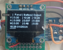
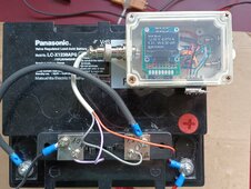
I have successfully implemented the INA226 Smart Shunt functionality and also the option to have OLED display locally.
1706386784423.pngEnjoy the new software at Github:

You configure the Smart Shunt with a shunt file placed in the libraries.
Code:
// SHUNT_1A_25mV

// ***Electrical parameters***   (Adjust, if you use other shunts than R100)
#define SHUNT0    25000      // Nominal Shunt resistor value in microOhm (Channel 1 of the INA, connected to the battery)
#define AMPERE0    5                // Max expected intensity in operation
#define IFACTORB   1000000   // Battery Current correction factor 1000000 is normal,  -1000000 reverses shunt, change value to correct for wrong Amp values

Normally it should immediately show the right values, you may trim the result by tweaking IFACTORB.

The OLED shows also the boot information and the assigned WLAN address, very useful if you have several devices to get in touch over Telnet.

The schematic for SmartShunt is here

Enjoy!
 
Last edited:
The Project gets new features.

- new OLED display arrangement when used as a smart shunt.IMG_20240202_090809.jpg
- BME 680 option to measure locally temperature / pressure / humidity

- Local Battery reporting on Telnet
Code:
$ telnet 192.168.188.27
Trying 192.168.188.27...
Connected to steroids.fritz.box.
Escape character is '^]'.

Waiting for input
B

 Battery Stats
 Hour   |  00   |  01   |  02   |  03   |  04   |  05   |  06   |  07   |  08   |  09   |  10   |  11   |
 Bat Ah | 12.43 | 00.00 | 00.00 | 00.00 | 00.00 | 00.00 | 00.00 | 00.00 | -0.00 | -0.01 | 00.01 | 00.39 |
 Bat V  | 12.46 | 12.45 | 12.43 | 12.43 | 12.43 | 12.42 | 12.42 | 12.41 | 12.41 | 12.33 | 12.45 | 12.86 |
 Hour   |  12   |  13   |  14   |  15   |  16   |  17   |  18   |  19   |  20   |  21   |  22   |  23   |
 Bat Ah | 00.27 | -0.03 | 00.57 | 00.62 | 00.46 | 00.02 | 00.00 | 00.00 | 00.00 | 00.00 | 00.00 | 00.00 |
 Bat V  | 12.97 | 12.37 | 13.73 | 13.72 | 12.79 | 12.56 | 12.51 | 12.50 | 12.48 | 12.47 | 12.47 | 12.46 |
V

Values Report
BatV:12.41 BatI:-0.02 BatW: -0.50 PanV: 14.31 PanI: 00.00 PanW: 00.00 LoadI: 00.00 LoadW: 00.00 IOhm: 0.0010
BatV:12.41 BatI:-0.02 BatW: -0.25 PanV: 14.37 PanI: 00.00 PanW: 00.00 LoadI: 00.00 LoadW: 00.00 IOhm: 0.0010
BatV:12.41 BatI:-0.02 BatW: -0.25 PanV: 14.45 PanI: 00.00 PanW: 00.00 LoadI: 00.00 LoadW: 00.00 IOhm: 0.0010
BatV:12.41 BatI:-0.04 BatW: -0.25 PanV: 14.53 PanI: 00.00 PanW: 00.00 LoadI: 00.00 LoadW: 00.00 IOhm: 0.0010
Q
bye bye
Connection closed by foreign host.
 
Back
Top