diy solar

diy solar

EG4 6500 EX Under an Oscilloscope

I know enough to be dangerous. Had a few minor “welding” instances when assembling my batteries and proved that 20 gauge electrical wire could in fact double as mig wire lol (had a deadline and I was forced to hurry).

This sh!t scares the crap out of me. I suppose that’s good. Complacency kills.
 
Do we have any updates on this very important thread?
Here was a pair of LV6548's on the same system. Only change was the inverters and PV power was cut in half from 8S to 4S to meet the 250V VOC rating.
 
How does the UL certification work if the output is not clean, clearly the 6500 EG4 out put is not clean, has nothing to do with bulbs.
 
How does the UL certification work if the output is not clean, clearly the 6500 EG4 out put is not clean, has nothing to do with bulbs.
UL probably just requires it turns on and doesn't catch fire and burn the house down.
 
No I'm quite certain there is more to that otherwise UL would be considered useless. I actually looked at HomeGrid certifications on there backup battery system it showed the entire PCB board and every component that is used on the board, down to the little rice sized SMD transistors.

not to mention fire test and more, so that being said if the UNIT has UL certifications, they would have each component used on the unit as part of the certification, this means if there is a hardware fault, it would be documented.

So maybe this was a production run thing? If they changed components would the UL certification go away and it need to be re-certified?
 
Is that the same as how Trace did it? I believe that their inverters actually contained three separate ones.

And if so, is this still how Schneider and Outback (the low frequency models) still work or did they change that?
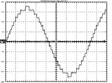
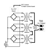
Yes, Trace originally patented the design of three series secondary side stacking, but patent is long expired. It creates 3^3 = 27 maximum voltage steps. Each of the three transformers can produce +V, 0, -V output, so the 15v, 45v, and 135v outputs are combined to give a rough stepped approximation of 120 vac rms AC sinewave. The 27 steps must encompass battery voltage and AC output voltage extremes so normally less than 27 steps are used for nominal battery and AC output voltages.

It works on principle of low leakage inductance for tightly coupled power transformers. When primary is shorted, the secondary is approximately shorted. Actually, there is some series leakage inductance in the ballpark of a millihenry series inductance plus secondary winding resistance.
Trace Step Sine Waveform 2.jpgTrace inverter driverr.png
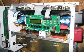
SW4048 front picture.jpg

Only weighs 105 lbs. for a 4 kW inverter. The 5.5 kW version weighs 136 lbs. But they are highly reliable and almost bulletproof.

Nobody uses this method anymore since it is more expensive and is not as clean a sinewave output. It does have the advantage of avoiding the issues with PWM filter ringing and lower idle current for inverter due to low switching frequencies and no reactive load from PWM L-C filter.

PWM switching with L-C filter is much cheaper.

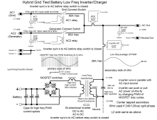
Big issue with PWM L-C filter, being LF or HF inverter design, is the L-C filter ringing when underdamped for lighter AC loads. The ringing screws up the ability to regulate the AC output voltage by inverter's AC voltage feedback control.

I believe the original Outback LF transformer PWM design used a LF transformer with purposefully increased leakage inductance by coating silicon-iron E core laminations with thicker varnish to create more leakage inductance eliminating the need for the high frequency, high current PWM primary side filter inductor.

In reality, it is often cheaper to use a standard stock LF transformer design and add the high current toroid PWM filter inductor to primary side.

Having the separate filter inductor allows fine tuning of L-C filter design. Some of the cheap Chinese LF inverters use the square box core LF power transformer design which has greater leakage inductance than 'E' core power transformers so they can eliminate the extra cost of high current toroid PWM filter inductor. This is part of the reason they have greater idle current.

Toroid LF power transformers have very low leakage inductance (like used in Victron inverters). They must use a high current toroid inductor for their PWM filter. They get lower idle current with this design. Toroid LF power transformers can be physically smaller for equivalent power handling capability, but they cost more so you will rarely see them in Chinese LF inverters.

inverter functional diagram.png
 
Last edited:
For instance, my inverter does not use any form of voltage feedback.
It uses voltage (and current) feed forward to regulate the output voltage.
Its much faster to respond and unconditionally stable, much more than than voltage feedback.
As far as I know my Warpverter design is the only inverter to use feed forward instead of feedback.
That is another very powerful technique that still seems to be unknown in the inverter design world for some reason.

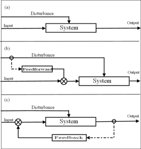
I like to get a better understanding of your feedforward design. Are you using input current and input voltage parameters to regulate output voltage?

290px-Control_Systems.png


Feedforward
 
No I'm quite certain there is more to that otherwise UL would be considered useless. I actually looked at HomeGrid certifications on there backup battery system it showed the entire PCB board and every component that is used on the board, down to the little rice sized SMD transistors.

not to mention fire test and more, so that being said if the UNIT has UL certifications, they would have each component used on the unit as part of the certification, this means if there is a hardware fault, it would be documented.

So maybe this was a production run thing? If they changed components would the UL certification go away and it need to be re-certified?
... and where in the HomeGrid cert ensures it produces high quality power? UL (and similar lab) testing is mostly focused on safety. A product can be completely crap in terms of features, performance and quality and still get UL approval if it's safe to use.
 
I like to get a better understanding of your feedforward design. Are you using input current and input voltage parameters to regulate output voltage?
Yes that is how my feed forward correction works.

The basic idea is to measure the dc voltage coming into the inverter, and generate a sine wave of constant amplitude from that value of dc.
If you think about that, it can easily correct for slow changes in battery voltage, as well as sudden sags and surges due to fast load changes.

For instance, if 48 volt dc incoming power suddenly increases to 50 volts dc, you know that is a four percent measured increase.
So all you need to do is adjust downwards the digital drive amplitude that generates the inverter switching waveforms by the exact same 4%. and the ac output should remain constant. This can work equally well with ordinary PWM, or the stepped waveform used by Trace or a Warpverter.

The advantages are, that its very fast and easy to measure a dc input voltage. Measuring ac is a lot slower, because its constantly varying over each cycle anyway, and you need to either average at least a whole cycle or just measure at the exact peak, which can lead to errors if the ac waveform is at all noisy or distorted. With feedback, there are other problems, that the speed of correction must be kept slow. If you over correct, feedback can become unstable. So how much correction, and how fast the correction is applied, must be very carefully tuned. In other words classic PID loop tuning.

None of these problems apply to voltage feed forward. You just measure the incoming dc, and instantly change the output amplitude to correct.
The output correction may not be exact ( it may end up half a volt high or low) but it corrects very fast and can never become unstable.
If you always correct the amplitude right at the zero crossing, large sudden step changes in amplitude can be made without introducing any waveform distortion.

Now all this assumes that the inverter is perfect. That it has no internal resistance that the output voltage does not droop with increasing load power.
If an inverter has say 95% efficiency, the internal power loss will be proportionally quite small, and the output voltage regulation pretty good.
So all you really need is voltage feed forward and that will be good enough for most applications without anything else.

My own 5Kw 230v Warpverter drops about 2v per Kw with just voltage feed forward. So from no load to flat out the ac voltage goes up and down by 10 volts. The grid goes up and down by more than that here, and everything still works fine. My system can correct over a 2:1 dc input voltage range, which is a lot more than most other inverters. It will run straight from direct raw solar voltage if there is enough sun to do it.

To improve things further, current feed forward can be added. This works in the exact same way as voltage feed forward. The dc input current to the inverter is measured with a Hall sensor, and that is used to further slightly correct the output voltage droop with load. increase.
In fact, its possible to over correct, if you wanted to do that, so that the inverter output voltage actually rises with increasing load.
That might be useful if the inverter is remote from the load ! It could be tweaked to compensate for wiring voltage drop.

The inverter works fine without any of that, but if you need perfect output voltage regulation with extremely fast correction, this is the best way to achieve it.

I have never seen or heard of another inverter using feed forward voltage control, and I just cannot understand why nobody else uses it.
Its a very common technique in many other types of industrial control systems.

Even the engine management in your car uses feed forward to adjust ignition timing and fueling.
All the inputs from rpm, engine load, temperature, and other things are measured, and the correct value for spark and fuel set from a lookup table. There is no feedback !! Your inverter could run the same way by measuring just dc input voltage and current, and setting the output voltage appropriately. No feedback required.
 
  • Like
Reactions: Cal
Even the engine management in your car uses feed forward to adjust ignition timing and fueling.
All the inputs from rpm, engine load, temperature, and other things are measured, and the correct value for spark and fuel set from a lookup table. There is no feedback !! Your inverter could run the same way by measuring just dc input voltage and current, and setting the output voltage appropriately. No feedback required.

Thanks for the explanation. As long as components are stable (temperature and aging), then feedforward will work well. I would feel better though if there's also feedback. Otherwise output voltage is guaranteed only under specific conditions. Feedback can also be adjusted at zero crossing.

The primary automotive fuel mixture sensors are the Lambda sensor (O2) and Mass Air Flow sensor (MAF). Lambda is feedback while MAF is feedforward.
 
Temperature and ageing should not be a problem, at least they have not been a problem here over the last five years or so.
The conduction losses in the inverter are not going to change much over time, probably the largest loss will be the resistance of the windings in the transformer. So if your 230 volts drifts up to 231 volts over time due to component ageing, that can easily be re tweaked.

None of the Warpverter builders have complained about voltage stability or regulation, so they seem to be as happy as I am with the whole feedforward concept. I must say I was quite surprised how well it worked from the very first experimental attempt.

The corrections for an engine management system will mostly be highly non linear, and have complex interactions which greatly complicates the whole predictive correction thing.

Our inverter only requires the simplest straight line correction. If the dc input voltage instantly drops by half, the ac output voltage also falls by half if left uncorrected.
Its not really necessary that a 230 volt output inverter is always exactly 230.00 volts. If it slowly wanders up and down by a volt or two from day to day, its still going to have a lot more stability than the grid !

Arguably, the much more important issue with inverter voltage regulation, is that the ac output voltage corrects very quickly for very large step changes in line or load, to minimise light flicker. That part works extremely well and is the single biggest advantage of feed forward over feedback.

Feedback can only correct what has already occurred, but by then its really too late.
Feed forward can almost anticipate the change in output, and react almost instantly to correct it.

It would also be possible to add very slow corrective feedback into a feed forward system to compensate for slow changes due to component ageing.
As Cal says, this is done in engine management units with an oxygen sensor to correct for slow engine wear and changing fuel quality.
Many things are possible, but for a domestic inverter, basic simple bare bones voltage feed forward is more than sufficient to do a good job.

Over complicating it for better performance is certainly possible, but in my opinion just not worth the trouble.
 
Last edited:
Arguably, the much more important issue with inverter voltage regulation, is that the ac output voltage corrects very quickly for very large step changes in line or load, to minimise light flicker. That part works extremely well and is the single biggest advantage of feed forward over feedback.

Feedback can only correct what has already occurred, but by then its really too late.
Feed forward can almost anticipate the change in output, and react almost instantly to correct it.

Not sure I agree. You're making corrections every half cycle, at the zero crossing. That is not immediate.

In a voltage sense feedback circuit the output peak voltage is measured. The correction can also be made at the zero crossing. There is no difference in delays.

Feedforward does not anticipate a change in output voltage any better than feedback. They are both reactive. It's a moot point anyways as you can only make corrections very half cycle.
 
Its a LOT more immediate than rectifying the ac, averaging it in an integrator over several or many cycles, comparing that to a reference voltage, then slowly ramping in the required change with a PID control loop that must be made gradual.

Well no, a voltage sensing feedback that takes a snapshot of the ac voltage right at the peak, can introduce huge errors if the waveform is distorted, or there happens to be a random noise spike right when you measure. And a PID feedback loop can never be made to correct quickly.

The same type of errors can creep in if you just take a snapshot of the incoming dc for a feed forward system. In my case, I use a dual slope integrating analog to digital converter that averages out any ripple or noise on the dc input. Its still much easier and much faster to accurately measure dc than ac voltage.

Here is a mental exercise for you to consider.
You are in an unfamiliar hotel for the first time and hope to take a shower.
To get the water temperature exactly right, you need to VERY SLOWLY adjust the taps, while testing the water temperature.
Wildly spinning the taps will not work, it has to be adjust, wait, test, adjust again. Patience is a virtue !
Feedback is always like that. You absolutely must correct very slowly wait for the adjustment to take full effect, and slowly zero in with your feedback.
If you try to speed things up, you can very easily over correct, and the whole thing just starts swinging from one extreme to the other (oscillation).

With an inverter, the delay in response is not in the inverter, but in accurately measuring the ac voltage in such a way that is immune to noise and distortion produced by "nasty" loads. Only then can you introduce your gradual voltage correction. If its not noise immune the output voltage will be all over the place, and you get to rethink the whole thing.

With feed forward in the same hotel situation, you could (theoretically) measure the incoming hot and cold water temperatures, the relative water pressures and degree of tap rotation to adjust appropriate flow. You could write the whole thing into a software algorithm that could predict exactly where both taps need to be set, to create the desired (fixed) discharge water temperature and flow. It may end up being a couple of degrees wrong, but it could be made to be extremely fast acting. Much faster than a gradual perturb and observe trial and error feedback system.

Sorry but you are quite wrong about feed forward being no faster to correct than feedback. If you had ever done any control loop tuning, you would know the difference between an over damped response, and a response that creates ringing. Its a fine art to get right, and feedback has to be gradually applied.

Feed forward is predictive, that is how it works.
It looks only at the inputs, decides what to do, and corrects perfectly all in one single step, or within the overall attainable accuracy of the system.
Feedback is like a perturb and observe algorithm, where you creep up on the desired outcome a bit at a time being careful not to over correct.

In our case we need only one input variable, dc voltage.
The correction is linear straight line correction.
It could not be any simpler.

If the dc input changes, we make a similar change to the "power gain" of the inverter in the opposite direction to correct for the original dc voltage change.
It may not always adjust precisely to the desired output voltage, but by golly it responds quickly without any possibility of oscillation or instability.
 
Last edited:
Sorry but you are quite wrong about feed forward being no faster to correct than feedback. If you had ever done any control loop tuning, you would know the difference between an over damped response, and a response that creates ringing. Its a fine art to get right, and feedback has to be gradually applied.


In our case we need only one input variable, dc voltage.
The correction is linear straight line correction.
It could not be any simpler.

Any closed loop circuit can be either over damped or under damped. It could occur in either a feedback or feedforward loop. It's up to the designer to get it straight.

After some thought, you are correct that an inverter design requires a stable dc voltage. Using one or more transformers, switching fets, and a regulated dc voltage, ac is generated. The stable voltage is generated from a boost regulator. The boost regulator has voltage and or current feedback control. The bode plot crossover frequency might be around 10 kHz. Doubt feedforward is any faster. Don't know if that's similar to what you have, but this design does not have a feedforward control loop.
 
Feed forward is not a loop.
That is the whole point.
Nothing is fed back from the output to control the inverter.

Not all inverters have or need a boost converter.
Most switch the incoming dc directly in one single stage, either for generating direct pwm to directly drive a low frequency transformer, or in the case of a stepped waveform generation such as Trace or a Warpverter, hard switching of multiple low frequency transformer primaries with appropriate drive waveforms.

Feed forward is only really appropriate for single stage dc to ac power conversion, where the ac output voltage then becomes directly proportional to dc input voltage. Its always more efficient to do it in a single switching stage if possible, no matter how the inverter works.

The biggest single disadvantage of a high frequency boost converters is they are very much peak power limited.
A 2Kw rated boost converter cannot supply 10Kw even for a very brief time.
That makes them unsuitable for many heavy duty applications that are required to source heavy surge loads such as starting up large motors.

But I agree with you, a voltage regulated boost converter is a cheap way to build an inverter, but it will be a fragile inverter.
It will also require internal voltage feedback, and would be unsuitable for voltage feed forward anyway.
 
@Warpspeed Sorry if you have posted it before, but what is the efficiency of your inverter? I get that 54 switching operations (at reduced current) are going to be more efficient than a similar number of PWM steps at full current, but curious how much it improves things over a hybrid PWM and 2-step modified sine wave.
 
@Warpspeed Sorry if you have posted it before, but what is the efficiency of your inverter? I get that 54 switching operations (at reduced current) are going to be more efficient than a similar number of PWM steps at full current, but curious how much it improves things over a hybrid PWM and 2-step modified sine wave.
Efficiency is a difficult thing to nail down, as a lot depends on at what power level you make the measurement.
My Warpverter nominal dc input voltage is 100v dc, that is for thirty Lithium cells. Design input voltage range is 90v to 180v.
No load idling power is 31 watts, at which point the efficiency is effectively zero.

With a thirty watt load, as you might expect the efficiency is about 50% and rises very steeply above that to a peak of around 95% or 96%.
I cannot remember where the peak was exactly (all this was almost six years ago) but it might have been around or just below 1Kw.
As I remember, running continuously flat out at 5Kw it was something like 92% measured at the time.
It will easily handle short term power surges of multiples of 5Kw, but I never tried to thrash it to the point of trying to find a point of actual failure !

Compared to the home made PWM transformer inverters the guys on The Back Shed have been building and testing over many many years, of similar rated output power, its pretty comparable in every respect. Not better or worse, pretty much identical performance in every way.

Its quite difficult to measure dc input and ac output voltages and currents to sufficient accuracy to get really dependable figures. A one percent error here, and half a percent error there, can really skew efficiency figures around. So its really pointless arguing that one persons measurement of 96% is actually any better than someone else's measured figure of 93% is real or imagined. So I do not really sweat efficiency numbers.

Its a sobering thought that to get from 96% to 98% overall losses need to be halved (go down from 4% to 2%) That can be quite difficult to do.
So it does not surprise me that figures cluster around the mid 90's for most sine wave inverters, and anyone claiming much higher might not be being completely honest. And peak efficiency might not be quite the same as efficiency measured at absolute flat out maximum power.

Conduction losses rise square law with current, so as power level increases it all becomes a lot more difficult.
How to lie and mislead with statistics, can be turned into a real art form.
 
Back
Top