diy solar

diy solar

Eg4 6500ex can't update firmware

shaggy745

New Member
Joined
Nov 5, 2022
Messages
104
Hi all,
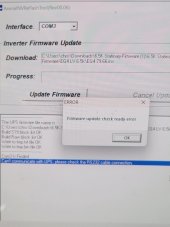
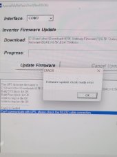
I'm having trouble updating the firmware on my 6500. I know the port is correct, but can't get my computer to connect. Using cable that came with inverter--direct USB to rj45.
I keep getting errors with both the inverter and the display panel update.

Any guidance?

TIA.
 

Attachments

  • 20230402_105440.jpg
    20230402_105440.jpg
    419.6 KB · Views: 28
  • 20230402_105440.jpg
    20230402_105440.jpg
    419.6 KB · Views: 28
Have you been able to update the firmware using the supplied cable before?

Does COM3 show up in Device manager?
 
You must be sure to use the correct cables!
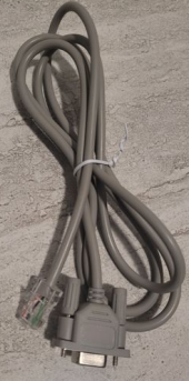
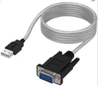
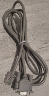
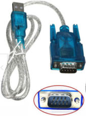
You need the EG4-special RS232 RJ45-to-DP9female cable which is included in each inverter package. You also need (buy separately!) a standard USB-to-RS232/DP9male cable and connect both together.

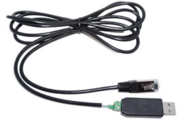
This is the EG4 inverter provided cable:
1680576732296.png

This is the additionally needed cable (not included):
1680575538483.png


Do not
use the following RS485 USB-to-RJ45 cable which you may also got from Signature Solar to flash the firmware for batteries! This is ONLY for flashing the BMS of EG4 batteries!!!
1680575669513.png

With the described cables I've successfully flashed the firmware of 9 EG4-LL V2 batteries and 6 EG4-6500EX inverters, last week.

Good luck!
 
Last edited:
Have you been able to update the firmware using the supplied cable before?

Does COM3 show up in Device manager?
First time updating firmware. Yup, COM3 registering in DM when the cable is plugged in.
 
You must be sure to use the correct cables!
You need the EG4-special RS232 RJ45-to-DP9female cable which is included in each inverter package. You also need (buy separately!) a standard USB-to-RS232/DP9male cable and connect both together.

This is the EG4 inverter provided cable:
View attachment 142854

This is the additionally needed cable (not included):
View attachment 142851


Do not
use the following RS485 USB-to-RJ45 cable which you may also got from Signature Solar to flash the firmware for batteries! This is ONLY for flashing the BMS of EG4 batteries!!!
View attachment 142853

With the described cables I've successfully flashed the firmware of 9 EG4-LL V2 batteries and 6 EG4-6500EX inverters, last week.

Good luck!
Ahh, I thought the bottom cable could be used for the inverter and it was only in older shipments of this inverter that you needed to go to serial and then back to RJ45. Frustrating that Signature Solar only provides half of the cable that you need! thanks for the input.
 
I think, SignatureSolar should include a direct USB-to-RJ45 cable (without converting it in between to DB9 and back).

Btw.
The same cable(s) which are required for flashing the inverter could be used to connect the inverter(s) to Solar Assistant. I've tried to make custom cables without the ugly and space-filling DB9 and with the right length and crimping the EG4 specific RJ45 pinout by myself (I want to permanent connect each of the six inverters to SolarAssistant separately to be able to query ALL possible data - when connecting only the master inverter you will get most, but not all parameters, e.g. the individual inverter temperatures, bus voltages, MPPT2 values).
But unfortunately, it's not so easy to build such custom cables. Most available cable headers are using USB-to-TTL which is NOT compatible with the EG4 required RS232 signal voltage level (I've tried that). Most of the available USB-to-RS232/DB9 adapters (see my 2nd picture of my 1st post) have the electronic in the DB9 connector, so I'm not able to just cut the DB9 and crimp with EG4 RJ45 pinout... still looking for a solution...
I tried the same thing. I wanted to make my own and save a few bucks. After 3 different attempts with 3 different cables, I ended up purchasing this one from Watts247 and it's worked flawlessly.

 
I tried the same thing. I wanted to make my own and save a few bucks. After 3 different attempts with 3 different cables, I ended up purchasing this one from Watts247 and it's worked flawlessly.

Yes, this is what I try to custom build with specific lengths - the cable from watts247 is really expensive (I need 6 of them), so I'm still trying to find a real USB-to-RS232 cable with header (or with electronic in the USB side connector and be able to remove to DP9 connecter and crimp an RJ45). This should be only between $5-$12 per cable (e.g. https://www.amazon.com/dp/B000A1KD1K or https://www.ebay.com/itm/255666926991).
 
Yes, this is what I try to custom build with specific lengths - the cable from watts247 is really expensive (I need 6 of them), so I'm still trying to find a real USB-to-RS232 cable with header (or with electronic in the USB side connector and be able to remove to DP9 connecter and crimp an RJ45). This should be only between $5-$12 per cable (e.g. https://www.amazon.com/dp/B000A1KD1K or https://www.ebay.com/itm/255666926991).
If you find one that works, please let me know.

I tried to modify these ones and they didn't work. I think I had the pinout either from Watts247 or from SA directly. Can't remember at the time. I had also compared to the pinout on the DB9.
 
The pinout is not really the problem (I've measured it and found the following pinout for the EG4 provided RJ45-to-DB9female cable):

RJ45 pin #DP9 pin #EG4 used wire colorRS232 signal name
12redRxD
23whiteTxD
46blackDSR
85greenGND

The voltage level looks like 7-8 Volts and with negative logic (negative voltage!).

The problem with the cables you've mentioned is about the TTL level of these cables - The USB-to-TTL it's not USB-to-RS232 (conversion from USB to TTL is only half of the way to convert USB to RS232)! So the goal is to find a real USB-to-RS232 (with pin header or with a DB9 connector without electronic inside the DB9 to replace it with RJ45 - the whole conversion electronic has to be in the USB connector case!).
 
Hi all,
I'm having trouble updating the firmware on my 6500. I know the port is correct, but can't get my computer to connect. Using cable that came with inverter--direct USB to rj45.
I keep getting errors with both the inverter and the display panel update.

Any guidance?

TIA.
It looks like you need the additional firmware cable. Can you send me an email at peyton@signaturesolar.com? I'll get with someone to get you a cable out.
 
The pinout is not really the problem (I've measured it and found the following pinout for the EG4 provided RJ45-to-DB9female cable):

RJ45 pin #DP9 pin #EG4 used wire colorRS232 signal name
12redRxD
23whiteTxD
46blackDSR
85greenGND

The voltage level looks like 7-8 Volts and with negative logic (negative voltage!).

The problem with the cables you've mentioned is about the TTL level of these cables - The USB-to-TTL it's not USB-to-RS232 (conversion from USB to TTL is only half of the way to convert USB to RS232)! So the goal is to find a real USB-to-RS232 (with pin header or with a DB9 connector without electronic inside the DB9 to replace it with RJ45 - the whole conversion electronic has to be in the USB connector case!).
Keep us in the loop!
 
Keep us in the loop!
I found a possible solution to build a EG4 custom length USB-to-RS232/RJ45 cable. It's not really 100% what I was looking for (I would prefer to have the whole electronic just in the USB connector case). This solution requires a TTL-to-RS232 voltage level change electronic in addition to an USB-to-TTL adapter. This electronic could be wired close to a common and easy to find USB-to-TTL stick (to hide both in the cable channel). With this I would be able to flexible crimp perfect length wires to the inverters without having these ugly DB9male-to-DB9female plugs in the middle of the cables.

This is the module which I've found (https://www.amazon.com/KOOBOOK-MAX3232-Converter-Adaptor-Transfer/dp/B07VNLVJ57 or this https://www.amazon.com/HiLetgo-Level-Converter-Board-Rs232/dp/B00LUDCAXQ as an alternative):
1680817666022.png

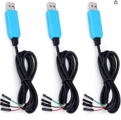
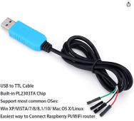
It could be connected to e.g such and standard UBS-to-TTL converter (https://www.amazon.com/dp/B07D9R5JFK?) to build the complete custom cable with crimping an EG4 RJ45 at the RS232 side of the above module.

1680818317671.png


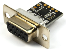
Usually these level converters come with an existing DB9 connector like this (https://www.amazon.com/Ultra-Compact-RS232-Converter-Female/dp/B00OPTOKI0) which would not help to build a custom cable (also it's female instead of male).

1680817951426.png

So I may try later (when everything else will be finished) to build such cables with the top shown modules.
 
Last edited:
I found a possible solution to build a EG4 custom length USB-to-RS232/RJ45 cable. It's not really 100% what I was looking for (I would prefer to have the whole electronic just in the USB connector case). This solution requires a TTL-to-RS232 voltage level change electronic in addition to an USB-to-TTL adapter. This electronic could be wired close to a common and easy to find USB-to-TTL stick (to hide both in the cable channel). With this I would be able to flexible crimp perfect length wires to the inverters without having these ugly DB9male-to-DB9female plugs in the middle of the cables.

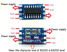
This is the module which I've found (https://www.amazon.com/KOOBOOK-MAX3232-Converter-Adaptor-Transfer/dp/B07VNLVJ57 or this https://www.amazon.com/HiLetgo-Level-Converter-Board-Rs232/dp/B00LUDCAXQ as an alternative):
View attachment 143428

It could be connected to e.g such and standard UBS-to-TTL converter (https://www.amazon.com/dp/B07D9R5JFK?) to build the complete custom cable with crimping an EG4 RJ45 at the RS232 side of the above module.

View attachment 143433


Usually these level converters come with an existing DB9 connector like this (https://www.amazon.com/Ultra-Compact-RS232-Converter-Female/dp/B00OPTOKI0) which would not help to build a custom cable (also it's female instead of male).

View attachment 143429

So I may try later (when everything else will be finished) to build such cables with the top shown modules.
Good luck!
 
Good luck!
It's not as easy as I thought...

I've used a standard USB-to-TTL like that (https://www.amazon.com/dp/B07D9R5JFK):
1681262373677.png

and tried to connect it to the left side of the following TTL-to-RS232 converter module (https://www.amazon.com/dp/B091TN2ZPY):
1681261701724.png
and crimped the 3-pins on the right side to the EG4 specific RJ45 pinout (1=RxD, 2=TxD, 8=GND - but no DSR signal for RJ45 pin 4!).
But I had no luck.

The special EG4-RJ45 inverter cable
1681262069032.png
uses 4-pins (1=RxD, 2=TxD, 8=GND and 4=DSR) but all TTL-to-RS232 converter modules which I was able to find are only using 3-pins (DSR is always missing) - but all standard ready-to-use USB-to-RS232 cables (like https://www.ebay.com/itm/255666926991, see picture below) support the DSR signal!
1681262984357.png

It looks like that the EG4 requires the DSR signal and I have no idea how to generate this signal (I've also tried to tie it to GND but this does not work). I don't want to destroy the case of my existing USB-to-RS232 cable with DP9 connector to find out how these standard USB-to-RS232 cables generate the DSR signal (on DP9 connector pin #6) because they are usually also only using the MAX3232 chip.

Does someone know how to deal with the DSR signal when converting TTL-to-RS232?
 
It's not as easy as I thought...

I've used a standard USB-to-TTL like that (https://www.amazon.com/dp/B07D9R5JFK):
View attachment 144303

and tried to connect it to the left side of the following TTL-to-RS232 converter module (https://www.amazon.com/dp/B091TN2ZPY):
View attachment 144296
and crimped the 3-pins on the right side to the EG4 specific RJ45 pinout (1=RxD, 2=TxD, 8=GND - but no DSR signal for RJ45 pin 4!).
But I had no luck.

The special EG4-RJ45 inverter cable
View attachment 144297
uses 4-pins (1=RxD, 2=TxD, 8=GND and 4=DSR) but all TTL-to-RS232 converter modules which I was able to find are only using 3-pins (DSR is always missing) - but all standard ready-to-use USB-to-RS232 cables (like https://www.ebay.com/itm/255666926991, see picture below) support the DSR signal!
View attachment 144306

It looks like that the EG4 requires the DSR signal and I have no idea how to generate this signal (I've also tried to tie it to GND but this does not work). I don't want to destroy the case of my existing USB-to-RS232 cable with DP9 connector to find out how these standard USB-to-RS232 cables generate the DSR signal (on DP9 connector pin #6) because they are usually also only using the MAX3232 chip.

Does someone know how to deal with the DSR signal when converting TTL-to-RS232?
I don’t. You got a lot farther than I did. It’s getting to the point that buying the cable is gonna be cheaper in the long run.
 
I don’t. You got a lot farther than I did. It’s getting to the point that buying the cable is gonna be cheaper in the long run.
I've found the solution. The DSR (pin 4 on the EG4 RJ45) has to be connected permanent to +5V with a pull-up resistor of 470 Ohm which could be soldered on the TTL-to-RS232 module between the right and left side (+5V/VCC is only available on the TTL side and has to be routed to the RS232 side of the module).

With this setup a custom length cable without using two DP9 connectors in between is possible to build. The module could be located very close to the USB-to-TTL stick.

But at the end, you're right! It's too much work and cost, which is not really worth to do it for six inverters. Additionally it would require a special case for the modules (3D printing would be an option). So I've decided to go with the existing cables and standard USB-to-RS232 extensions and live with the "ugly" double DB9 connectors in between (which are visible when connecting 6 inverters individually to SolarAssistant).

At the end, I've learned something...
Really appreciate you digging in and sharing what you found!
 
Back
Top