diy solar

diy solar

EG4 Chargeverter

I have some questions in reguards to SS's Chargeverter that recently came out. I plan to have a relatively simple setup at some remote property I own...or at least I hope everything is as simple as I have it in my head. I plan to use an EG4 6kW inverter, (2) EG4 LL 48v 100Ah batteries, and about 3kW of PV panels. I have read on here that the EG4 inverter/chargers do not like AC input from generators. I will be using a 7.5kW 1800 rpm diesel generator to top off the batteries as needed. On the surface it would seem (to me) the solution is their new 100A "Chargeverter". However, I read in another post that this unit does not charge at a high enough voltage to equalize all of the cells in a LiFePo4 battery such as the one mentioned above.
Another question I have is how does this charger know when to stop charging? I am pretty new to all of this and maybe everything is not straight in my head. My understanding is that there is a communications link between the batteries and the inverter/charger. It is my understanding that this BMS from the battery tells the inverter/charger when it's full and when to stop charging, or maybe when to go into a float charge. It is also my understanding that this Chargeverter plugs into my generator on the input side, then attaches to the bus bars my batteries are connected to on the 48v DC output side. If that's the case, how do the batteries tell the chargeverter when to stop charging? Maybe I'm missing something simple here? Also, is there any reason why I could not use this system I have described without any solar panels attached? My usage will be very minimal. A small TV and dvd player for a few hours in the evening, a few LED lights, a Starlink satalite internet router and dish, and a phone charger. It seems like I could run this off the 2 batteries for several days, then kick on the generator for a few hours and recharge the batteries for another 2 or 3 days. SS sales woman said no. She said I HAVE to have solar input for the EG4 to work.
Why is this called a ChargeVerter when it appears to be just a charger!
 
Yeah it’s definitely not for everyone… or even most people. But if you know a thing or 2 about micro controllers and canbus and want a fun project then the Huawei rectifier might be a good choice.
If / when you get your project started, it would be great if you would start a new thread to keep us updated.

The Victron Multiplus IIand Conext XW Oro allow charge power to be controlled via Modbus commands but I’ve been seeking a controllable charger-alone for some time now.

Someone told me these new chargers being offered by Signature Solar allow charge power to be controlled via CANBus but I can’t find and reference to that in the manual (nor even an RS485 or CANBus communication port).

So if you have the wherewithal to control a Huawei rectifier or any other low cost, reasonable efficiency rectifier or charger to consume excess solar export using communication / commands, there is at least one other member here who is not part of ‘everyone’ and would be interested in your solution…
Is this the sort of Huawei rectifier module you are talking about using: https://www.beyondlogic.org/pdf/Huawei_R4850G2_Rectifier_User_Manual_V1.4.pdf

It has CANBus communication and states that: ‘The output voltage can be adjusted by the host’ as well as ‘Digital Control Mode’, ‘Supports CAN Communication’, and ‘Supports voltage adjustment, current adjustment.’

Capable of absorbing up to 3kW of 240VAC export at efficiency of 95% and at a cost of $100, if one of these can be easily controlled via CANBus commands from a PLC, it is an interesting alternative to excess export control I was not aware of.

Do you have a manual containing the CANBus commands or how do you know the commands to use?
 
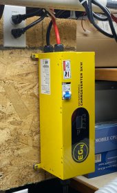
I just got my EG4 Chargeverter and ready to mount. I didn't read every post but wondering if there's a consensus on mounting - horizontal or vertical.

Is horizontal mounting (as LED panel is oriented) good enough? or is there a big plus for vertical mounting. @DavidPoz says he's going for vertical at the end of his review observing air flow out the DC end. .
Mine will also be mounted vertical, observing air flow.
It might not be necessary, but these things make a lot of heat. And I hope that it will extend the life.
 
Mine will also be mounted vertical, observing air flow.
It might not be necessary, but these things make a lot of heat. And I hope that it will extend the life.
Yea, there's something to be said for common sense - I'm going to mount vertically to give the best chance of cooling. It's interesting the little manual that came with it doesn't mention mounting orientation.
 
It's interesting the little manual that came with it doesn't mention mounting orientation.
I assume that the display and labeling, says how they expect it to be mounted.
I'm just going a step better.
If something goes wrong and it shuts down for some reason. I want it to passively cool itself as quickly as possible. So that hopefully nothing is permanently damaged.
 
Yea, there's something to be said for common sense - I'm going to mount vertically to give the best chance of cooling. It's interesting the little manual that came with it doesn't mention mounting orientation.
Got the EG4-Chargeverter Mounted vertically - used 1/4" spacers for air-flow behind it.
Just did a test using a Champion 100297 on propane and it pulled 25a @ 240v (6000w) to do 55v @ 100a (5500w) of charging. That's ~91% efficiency. Really pleased :)
1682797762100.png
This model Champion is an open-frame 'dirty' sine wave and 6000w is ~83% of 7250w max running for propane - so it seems a good match for fuel->charging efficiency. Need to work on heat/sound issues for the generator shed and then I can do some multi-hour tests.
 
Last edited:
What did,you,use as spacers? Washers? Nuts?

side note: does anybody know the chargeverter dc cable size? Or what size the eyelets are? 5/16?
 
What did,you,use as spacers? Washers? Nuts?
Nuts

side note: does anybody know the chargeverter dc cable size
They are 6.5ft long.
125a breaker.
They looked a little bigger than 4 AWG to me but I don't have a way to measure.
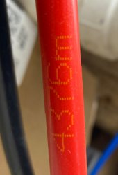
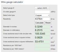
Red wire marking.... wild speculation, (https://www.rapidtables.com/calc/wire/wire-gauge-chart.html) could this be 4375m Resistivity? If so, copper ~ 53.5mm2 which is 0 AWG
1682899320850.png1682899545690.png
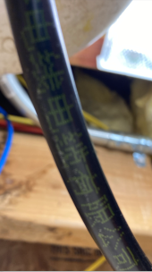
Black wire marking
1682899347529.png

Or what size the eyelets are? 5/16?
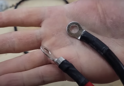
Yes, ~5/16 size. Here's a pic from @DavidPoz youtube
1682898638243.png


When I'm able to do some mulit-hour tests I'll try to do some heat monitoring and report back :)
 
Last edited:
Nuts


They are 6.5ft long.
125a breaker.
They looked a little bigger than 4 AWG to me but I don't have a way to measure.


Yes, ~5/16 size. Here's a pic from @DavidPoz youtube
View attachment 147261


When I'm able to do some mulit-hour tests I'll try to do some heat monitoring and report back :)

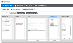
the pictures of this on sigsolar’s web site shows “22-8” stamped on the rings/lugs. I’m guessing the 8 is M8? (or 5/16) what would the 22 be?
 
What did,you,use as spacers? Washers? Nuts?

side note: does anybody know the chargeverter dc cable size? Or what size the eyelets are? 5/16?
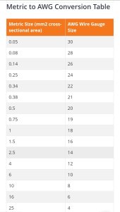
25mm² or 4awg
 

Attachments

  • Screenshot_20230503_185225_Edge.jpg
    Screenshot_20230503_185225_Edge.jpg
    109.4 KB · Views: 2

diy solar

diy solar
Back
Top