AGREE!!!!!! tagged Will and Super so they'll see just how great it is and hopefully do so... @Will Prowse @SupervstechShould probably sticky filterguys picture somehow.
You are using an out of date browser. It may not display this or other websites correctly.
You should upgrade or use an alternative browser.
You should upgrade or use an alternative browser.
EG4 Chargeverter
- Thread starter thepartyhound
- Start date
Zapper77
Renaissance Man
- Joined
- Jul 23, 2022
- Messages
- 2,341
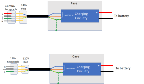
Can you make the plug in your diagram x,y,g,n reflect accurate colors on the left side. That way it's obvious for US based customers that black and red goto brown and blue for the 240v and black and white for the 120v.The inverter can be modeled like this:
View attachment 139060
Notice that the Blue and the Brown wires are isolated from the case and the neutral is not used at all. Also note that the charging circuitry can take anything from 90-265V AC.
Personally, I would not try to make an adaptor if I wanted to run this on 120V. Instead, I would replace the plug.
View attachment 139061
It does not matter electrically, but notice that putting the blue wire to the neutral prong of the plug best follows the international standard.
This could use a standard 15A plug but the charger would have to be configured to limit the input to 15 Amp. However, I would seriously consider using a higher amperage plug. A 20 amp would still require limiting the charger but a 30A plug would allow the charger to operate at it's full 120V capability.
Edit to add the X is considered primary black and Y is secondary red. Unless you are in Houston, TX...they do it backwards.
timselectric
If I can do it, you can do it.
- Joined
- Feb 5, 2022
- Messages
- 19,084
Everything is big in Texas.
Even their mistakes. lol
Even their mistakes. lol
And if we’re giving away free Chergeverters I think @timselectric should get one since his many answers were on point.
timselectric
If I can do it, you can do it.
- Joined
- Feb 5, 2022
- Messages
- 19,084
I never say no to free stuff. lol
FilterGuy
Solar Engineering Consultant - EG4 and Consumers
Too funny... I have a feeling he wanted you to map your connections to this drawing.
I’d like to know who, where, what, when, how you are using to make this ^ and all of the other pictures and diagrams in your awesome downloadable guides?
when I finally decide what I’m doing I’d like to be able to do this. Sadly I may have to resort to napkin diagrams, and taking a picture with my iPhone.
seriously your work is spectacular!
thanks for all,of the guides you’ve uploaded.
I agree, his work is excellent!!!!!seriously your work is spectacular!
Absolutely! I’ve downloaded all his stuff. The grounding made easier stuff helped me out a lot.I agree, his work is excellent!!!!!
and for real I emailed signature and told them he should get a CV. Lol.
or at least put his stuff in their manual which I found confusing Especially after Ben got the colors wrong.
FilterGuy
Solar Engineering Consultant - EG4 and Consumers
I use PowerPoint. I have tried using more formal schematic drawing tools but I find that I can make clearer diagrams with PowerPoint.I’d like to know who, where, what, when, how you are using to make this ^ and all of the other pictures and diagrams in your awesome downloadable guides?
when I finally decide what I’m doing I’d like to be able to do this. Sadly I may have to resort to napkin diagrams, and taking a picture with my iPhone.
seriously your work is spectacular!
thanks for all,of the guides you’ve uploaded.
I will often use the snipping tools that ships with Windows to snip a picture from the web and paste it into the drawing
Once I have the diagram I want there are a few ways to get it into the forum.
* At least in windows you can select all the elements in the PowerPoint drawing and then copy and past into the forum
* You can use the clipping tool to copy the image and past it into the forum
* You can save to PDF to upload to the forum
Note: I have not used it much but Google Slides works with the same file format as PowerPoint.
FilterGuy
Solar Engineering Consultant - EG4 and Consumers
Filterguy, I forgot to ask… you mentioned the blue neutral best followed international standards. I just did a brief google-fu and only the uk uses blue for a neutral.
what is/ where can I find this international standard?
Google the IEC (International Electrotechnical Commission). I am 99% sure it is in there and it is used throughout UK and the EU.
Unfortunately, it is *a* standard but not world wide.
The nice thing about standards is that if you don't like a particular standard, you can just use a different one.
timselectric
If I can do it, you can do it.
- Joined
- Feb 5, 2022
- Messages
- 19,084
It's also now used for a lot of led lighting.Google the IEC (International Electrotechnical Commission). I am 99% sure it is in there and it is used throughout UK and the EU.
Sold here in the states. Because they use a wide voltage range. And are using isolated drivers.
FilterGuy
Solar Engineering Consultant - EG4 and Consumers
Yes. It has been found in appliances here in the states for quite a long time, but I am definitely seeing it more than I used to.It's also now used for a lot of led lighting.
Sold here in the states. Because they use a wide voltage range. And are using isolated drivers.
timselectric
If I can do it, you can do it.
- Joined
- Feb 5, 2022
- Messages
- 19,084
YupYes. It has been found in appliances here in the states for quite a long time, but I am definitely seeing it more than I used to.
More and more every day.
Zapper77
Renaissance Man
- Joined
- Jul 23, 2022
- Messages
- 2,341
Just the way @FilterGuy did it. Except switch the x and y. X should be represented by black and y by red. But it works either way, just most plugs and receptacle are labeled with the letters x,y,n,g. And somebody is going to say, "I'm confused" because their house has a pre-wired receptacle with black on X and not Y as shown.Too funny... I have a feeling he wanted you to map your connections to this drawing.


Last edited:
Filterguy, I forgot to ask… you mentioned the blue neutral best followed international standards. I just did a brief google-fu and only the uk uses blue for a neutral.
what is/ where can I find this international standard?
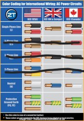
IEC uses Blue as a neutral. It's also in the new code in Australia since that one tries to mirror IEC. In places like Belgium, Finland, and other places in the EU it's been used since forever.
FilterGuy
Solar Engineering Consultant - EG4 and Consumers
Just the way @FilterGuy did it. Except switch the x and y. X should be represented by black and y by red. But it works either way, just most plugs and receptacle are labeled with the letters x,y,n,g. And somebody is going to say, "I'm confused" because their house has a pre-wired receptacle with black on X and not Y as shown.
View attachment 139101
View attachment 139102
I assume the implication is that the wire that is connecting to the blue wire in the cord is 'secondary'...?? I guess one could say that but I am curious if there is a standard for mingling the standards like this... I am not aware of one. As you say, it works either way.
timselectric
If I can do it, you can do it.
- Joined
- Feb 5, 2022
- Messages
- 19,084
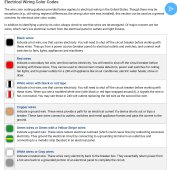
It's more of a color coding standard.

 electricalfundablog.com

Wiring Color Codes - USA, UK, Europe & Canada Codes, When to Apply
This post will discuss what are Wiring Color Codes, regional wiring color codes in USA, UK, Europe & Canada and when should we apply these codes.
 electricalfundablog.com
Similar threads
- Replies
- 2
- Views
- 225
- Replies
- 42
- Views
- 2K
- Replies
- 1
- Views
- 180
- Replies
- 1
- Views
- 421


