diy solar

diy solar

EG4-Lifepower4 Battery Bank Fuse Size?

JBoffgrid2022

New Member
Joined
Oct 28, 2022
Messages
216
Hello All!
I have four EG4-Lifepower4 48v 100A batteries coming to me soon and I would love some advice on fuse sizing. I have done some research already and have found some are saying I will need a fuse, some say don't bother. If I don't need a fuse, great, I'll skip this step! But if I do, I would love some direction on sizing and placement of these fuses. I'll be using 1/0AWG battery cables connecting my battery bank to a bus bar. From the bus bar, I will use the same size cables going into both inverters. Thank you!!

My setup:
-(2) EG4 6000XP Inverters in parallel
-(4) EG4 Lifepower4 48v 100A batteries (wired in parallel inside of server box)
-1/0 AWG cables connecting server rack to buss bars, then bus bars to inverters
One key to your question is the two 6000XP inverters.

Assuming a 95% efficiency, the max draw will be (6000/.95)/48V=131.6A each (263A total)
If you max out the PV, the max charge current is specified at 125A each (250A total)

Since the charge current is the greater value, we use that for calculating the battery fuse and wire size.

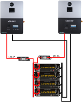
The next step is to determine how they are going to be wired. 1/0 Cable will never be able to carry 263A, so lets see if we can make it work with all the wiring in parallel. (I am assuming there will be a cabinet with busbars).

1702181900214.png


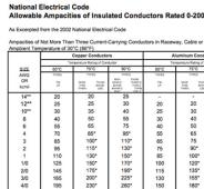
The fuses should be rated for 1.25 x 131.6 = 165A. That will have to be rounded up to 175A Class T fuse. The wire should be rated for 175A. Let's see if 1/0 can handle 175A by checking the NEC Ampacity Chart.

1702182219097.png

Technically, even if the insulation is rated at 90c, a 1/0 cable is too small.

Would 1/0 | 90c work? Yes.

Would 1/0 | 90c be safe? According to the NEC, NO. According to ABYC, YES.

What would I do?
  1. If I had not purchased the wire yet, I would buy 2/0 wire.
  2. If I already had the wire and it did not have at least a 90C rating, I would buy 2/0 wire and save the 1/0 for some future use.
  3. If I already had the wire and I had to pass inspection, I would buy 2/0 wire and save the 1/0 for some future use.
  4. If I already had the wire, it had at least a 90C rating, I did not have another use for it, and I did not have to pass inspection, I would probably go ahead and use it.
 
Thank you FilterGuy!!
Another save by a unknown genius (Or maybe known, just not to me! :ROFLMAO:)
I was very under educated on wire sizing when I ordered my battery cables... For some reason I thought the larger the wire the better it will transfer large amounts of amperage. Thank you for such a detailed easy to understand explination of this, I will look it over in detail and let you know if I have more questions.
 
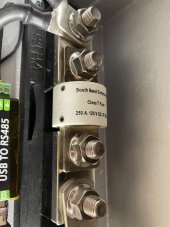
The South Bend T class fast blow fuses are high quality and I have used them with no problems. Littlefuse is higher quality. IMHO, there is NO substitute for a Blue Sea T class fuse holder! This is not a place to save money
 
There was a shortage of fuses and I wasn’t going to pay extortionist prices so South Bend it was.
IMG_1162.jpeg
 
For some reason I thought the larger the wire the better it will transfer large amounts of amperage.
2/0 is an abbreviation for 00 and 2/0 is larger than 1/0. 3/0 is larger than 2/0.

The AWG system is pretty screwy. I like the way the rest of the world does it.... but we use it in the US so it is what it is.

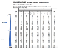
in awg smaller is better larger till you get to 0. Then you get larger with each additional 0. 2/0 is an abbreviation for 00 and 2/0 is larger than 1/0. 3/0 is larger than 2/0. The system stops at 4/0 and switches over to kcmil where larger numbers are larger wires.
1702233235299.png

You should get a 175A fuse and a quality holder

The first link was a 200A fuse and a holder.
The 2nd link was a holder for 200A or larger fuses. (The size of class T fuses gets larger starting at 200A so you have to be sure to get the right holder for the size fuse you will be using.

Edit: Corrected the fuse name
Note: You will see 2-Bolt and 4-Bolt class C T fuse blocks. The 2-bolt fuse blocks tend to be lower cost but I prefer the 4 Bolt holders because you can remove the fuse without taking the wire off. The one small technical advantage of the 2-bolt fuse is that there are fewer connections in the system. (The wire lug goes directly on the fuse, not to a busbar, and then to the fuse.)
 
Last edited:
When you tighten the nuts on a Blue Sea fuse holder, they feel very solid. Other brands feel mushy and should be recycled.
 
I have placed an order for these components. Thank you guys so much!!!
While I have your attention lol, could you briefly explain the best practice for grounding solar panels on a metal roof? I currently have them all connected with an aluminum racking system, tied into a #6AWG bare copper wire that runs straight down the roof and into the same ground rod that my main breaker panel ground is connected to. I was told DO NOT have two separate grounding rods because if lightening strikes, it will pass the through the system (frying everything in its' path including inverters, batteries, etc.) instead of traveling directly to the grounding rod. Let me know what you think, thank you all! @Skypower @FilterGuy
 
Last edited:
I just found your document on "Grounding Basics" @FilterGuy. I'll look this over and let you know if I have more questions, I'm pretty sure my answer is in this document lol. Thank you for posting this!!!
 
One key to your question is the two 6000XP inverters.

Assuming a 95% efficiency, the max draw will be (6000/.95)/48V=131.6A each (263A total)
If you max out the PV, the max charge current is specified at 125A each (250A total)

Since the charge current is the greater value, we use that for calculating the battery fuse and wire size.

The next step is to determine how they are going to be wired. 1/0 Cable will never be able to carry 263A, so lets see if we can make it work with all the wiring in parallel. (I am assuming there will be a cabinet with busbars).

View attachment 182064


The fuses should be rated for 1.25 x 131.6 = 165A. That will have to be rounded up to 175A Class T fuse. The wire should be rated for 175A. Let's see if 1/0 can handle 175A by checking the NEC Ampacity Chart.

View attachment 182065

Technically, even if the insulation is rated at 90c, a 1/0 cable is too small.

Would 1/0 | 90c work? Yes.

Would 1/0 | 90c be safe? According to the NEC, NO. According to ABYC, YES.

What would I do?
  1. If I had not purchased the wire yet, I would buy 2/0 wire.
  2. If I already had the wire and it did not have at least a 90C rating, I would buy 2/0 wire and save the 1/0 for some future use.
  3. If I already had the wire and I had to pass inspection, I would buy 2/0 wire and save the 1/0 for some future use.
  4. If I already had the wire, it had at least a 90C rating, I did not have another use for it, and I did not have to pass inspection, I would probably go ahead and use it.

Hrm. I have an SPH8K48SP with a rated power output of 8,000W and a max output power of 16,000W.

The owner's manual for this device lists "Max Battery Inverter Efficiency" at 92%.

By the calculation you provided, I should be sizing wires and fuses for (16,000W / .92) / 48V =~ 362A.

Can I get a sanity check on that?
I look at the continuous current rating for sizing the fuse. In your case it would be (8000/.92)/48 = ~181A.
 
That's an interesting point. If the inverter is rated at a max output power (even for a few seconds) of 16kw, how would this not blow a fuse that is rated at 181A? Are the parameters factored into this size fuse for large temporary draws?

Not doubting your logic, just curious how it works! :)
 
That's an interesting point. If the inverter is rated at a max output power (even for a few seconds) of 16kw, how would this not blow a fuse that is rated at 181A? Are the parameters factored into this size fuse for large temporary draws?

Not doubting your logic, just curious how it works! :)

I don't know the full spec, but it is probably 16KW for 1/2 sec. Most fuses would not even notice that. The fusible link just does not heat up that fast. Also, the calculation I show above is for worst-case continuous current. A fuse should be sized for 1.25 x worst-case continuous current so for the situation we are talking about it is ((8000/.92)/48) x 1.25 = 226.5A. That would need to be rounded up to a 250A fuse....nearly 100A over the normal current. The surge has to get 90A over the normal rating and hold it there long enough to blow the fuse.

However, some fuses are designed to be Fast-blow.... and that brings me to a nagging concern I have about my calculation and how it applies to Class T fuses. Class T. is known to be a fast blow fuse.... but I have never dug deep into what its characteristics are because I have don't hear reports of a Class T blowing due to load surges. Someday I am going to research just how fast Class T fuses are. In this case, the peak surge is 45% over the fuse trip point. How fast would that trip a Class T fuse?
 
Ok, that makes perfect sense. It's interesting to see all of the complex ins and outs of solar/electricity... You could spend a lifetime researching this and still not know it all lol! I'd be interested in knowing what you find out regardless.
 
Ok, that makes perfect sense. It's interesting to see all of the complex ins and outs of solar/electricity... You could spend a lifetime researching this and still not know it all lol! I'd be interested in knowing what you find out regardless.
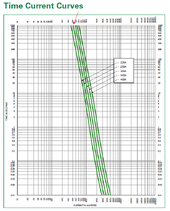
OK.... I went and found a trip curve for a 250A class T. At 400A the trip time is over 1000 Seconds. There is nothing to worry about for load surges.

1703293782334.png
 
That's an interesting point. If the inverter is rated at a max output power (even for a few seconds) of 16kw, how would this not blow a fuse that is rated at 181A? Are the parameters factored into this size fuse for large temporary draws?

Not doubting your logic, just curious how it works! :)

I think if I put a Class T inline it can take bit of overcurrent before failure.
OK.... I went and found a trip curve for a 250A class T. At 400A the trip time is over 1000 Seconds. There is nothing to worry about for load surges.

View attachment 184637

Thanks for this! Very useful for planning.

New to everything, but a 250A fuse tolerating 750A overcurrent for 16 minutes seems like a bad situation if you're fusing to prevent equipment damage.
 
New to everything, but a 250A fuse tolerating 750A overcurrent for 16 minutes seems like a bad situation if you're fusing to prevent equipment damage
It is the unusual case that fusing can prevent equipment damage. Fusing is primarily for protecting wires from overheating.... and that is a slow process. About the only thing that would cause 750A on the described circuit is a short and 99+% of the time it will be way above 750 A. The other factor is that the Inverter will shut down in way less time.
 

diy solar

diy solar
Back
Top