


You are using an out of date browser. It may not display this or other websites correctly.
You should upgrade or use an alternative browser.
You should upgrade or use an alternative browser.
Electrodacus SBMNS0 1 or 2
- Thread starter APhoton
- Start date
guyman
He's not much, but he's all we've got
I might be wrong, but 8S is a 24V battery not 12V
You are correct, 8S = 24v8S is a 24V battery not 12V
Op, in your current configuration, you would have 2 x 24v 8 cell batteries, each would need its own BMS, or you could reconfigure into a single 2P8S pack with a single BMS (this would be Dacian's reccomendation I believe, but may be the less popular option on this forum currently). Might be worth further research, if you haven't weighed your options.
What I have read on forum 2p8s or 8s2p is that it is best to go with 8s2p with two Electrodacus SBMNS0. This way each cell is balanced individually.
One other question that constantly confuses me and my apologies if this has been answer a 1,000 times. Wire sizing: I use "https://www.solar-wind.co.uk/info/dc-cable-wire-sizing-tool-low-voltage-drop-calculator" to calculate wire size. Where I alway get confused on is amps number.
1. My inverter/charger is 24v 3000w 9000w surge so do I use 125a (3,000/24) which means a 4 awg wire (3% loss) or do I use 375a (9,000/24) which means 4/0 awe wire (3% loss)? Manufacture recommends a wire of 1 to 2/0. This wire would run from battery bank to inverter and from inverter back to battery bank
2. My Voltage Converter Regulator DC 24V to DC 12V 40A 480W. Do I add 40a onto calculation of inverter charge-125a + 40a=165 (2 AWG wire) or 375a + 40a=415a (4/0 AWG wire)?
Attachments
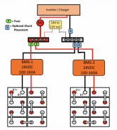
Its not quite that simple, but that is definitely a valid and logical approach. Individual cell balancing and redundancy are two of the primary benefits of this approach (disadvantages include added cost and complexity). Particularly with the 280Ah grey market cells, which are large capacity and only loosely matched.What I have read on forum 2p8s or 8s2p is that it is best to go with 8s2p with two Electrodacus SBMNS0. This way each cell is balanced individually.
Dacian (Electrodacus -- the maker of the BMS you are considering) argues that the advantages of 'series first' are overstated, particularly considering that internally a prismatic cell is a bunch of lifepo4 cells in parallel, so the idea that you achieve 'true cell level monitoring/balancing' with non-paralleled packs of large capacity prismatics is an illusion. While I can't argue with his point, I think his argument carries more weight with higher quality matched cells, there are other reasons to consider series first if you are buying large capacity loosely matched grey market cells which may require much more balancing than matched cells would. This last point isn't a point in support of or opposed to series first, what it supports is the idea that with unmatched packs, keeping down the size of what your BMS sees as a 'cell' is more important, this can be accomplished through not paralleling cells, or using smaller cells. I'm not an expert on this and also not able to speak on Dacian's behalf, just sharing (hopefully accurately) what I recall reading elsewhere, mixed in with some of my own thoughts towards the end.
Wire sizing is actually fairly complicated beyond the basics, so it is understandable to be confused. There are many variables to consider and some grey areas.One other question that constantly confuses me and my apologies if this has been answer a 1,000 times. Wire sizing: I use "https://www.solar-wind.co.uk/info/dc-cable-wire-sizing-tool-low-voltage-drop-calculator" to calculate wire size. Where I always get confused on is amps number.
Personally, I would look at the manufacturer recommendation as a floor that I would not go below but may choose to exceed.
This will depend somewhat on your inverter. My guess based on the numbers you provided is that you have an Sigineer/Aims/Sungoldpower or Yiyen inverter. I believe these have a 20 second surge rating.1. My inverter/charger is 24v 3000w 9000w surge so do I use 125a (3,000/24) which means a 4 awg wire (3% loss) or do I use 375a (9,000/24) which means 4/0 awe wire (3% loss)? Manufacture recommends a wire of 1 to 2/0. This wire would run from battery bank to inverter and from inverter back to battery bank
With a high frequency inverter you would use the continuous power rating (in this case 3000W), but with a low frequency inverter with high surge rating and duration, its a bit more of a grey area, since a surge could theoretically be many seconds or even minutes depending on the inverter.
One thing I notice off the bat is that you forgot to account for inverter inefficiency. This needs to be considered since an output of 3000W will require much more than 3000W on the DC input side. This is one of the most commonly overlooked factors. Generally I use 80% or 85% to ballpark inverter efficiency.
So the math would look something like 3000W / 0.80 / 24v = ~160A
I would (for wiring/fuses that will carry both the inverter and DC current). Some consider the inverter a good enough ballpark estimate because many people don't have substantial DC loads or assume they won't be running when the inverter is maxed out. Both approaches are acceptable in certain contexts, and have pros/cons. I tend to err on the side of caution, and the first option is definitely the more prudent, and some would say more correct approach.2. My Voltage Converter Regulator DC 24V to DC 12V 40A 480W. Do I add 40a onto calculation of inverter...?
The way I approach total system current calculations:
1. Calculate max AC current:
[inverter max power / low voltage cutoff / inverter inefficiency] = AC Total
2. Calculate max DC current:
[DC distribution max / inefficiency (if applicable)] = DC Total
*(where DC distribution max can be DC-DC converter amp rating, fuse block rating, or total calculatred dc loads)
Combine AC total and DC total to get theoretical max system current.
Thanks Dzi, this make it much clearer! Yes, I for got about is inventory inefficiency. So based on your suggestion calculator suggests 1 AWG but looking at https://www.engineeringtoolbox.com/wire-gauges-d_419.html 1 AWG Typical Max. Current Load Ratings - Copper is 180a. I'm calculation 225a usage so I need to move up to at least 2/0. Since manufacture recommends a wire of 1 to 2/0, I think 2/0 would work. Maybe I should think about 3/0 just for good measure??Its not quite that simple, but that is definitely a valid and logical approach. Individual cell balancing and redundancy are two of the primary benefits of this approach (disadvantages include added cost and complexity). Particularly with the 280Ah grey market cells, which are large capacity and only loosely matched.
Dacian (Electrodacus -- the maker of the BMS you are considering) argues that the advantages of 'series first' are overstated, particularly considering that internally a prismatic cell is a bunch of lifepo4 cells in parallel, so the idea that you achieve 'true cell level monitoring/balancing' with non-paralleled packs of large capacity prismatics is an illusion. While I can't argue with his point, I think his argument carries more weight with higher quality matched cells, there are other reasons to consider series first if you are buying large capacity loosely matched grey market cells which may require much more balancing than matched cells would. This last point isn't a point in support of or opposed to series first, what it supports is the idea that with unmatched packs, keeping down the size of what your BMS sees as a 'cell' is more important, this can be accomplished through not paralleling cells, or using smaller cells. I'm not an expert on this and also not able to speak on Dacian's behalf, just sharing (hopefully accurately) what I recall reading elsewhere, mixed in with some of my own thoughts towards the end.
Wire sizing is actually fairly complicated beyond the basics, so it is understandable to be confused. There are many variables to consider and some grey areas.
Personally, I would look at the manufacturer recommendation as a floor that I would not go below but may choose to exceed.
This will depend somewhat on your inverter. My guess based on the numbers you provided is that you have an Sigineer/Aims/Sungoldpower or Yiyen inverter. I believe these have a 20 second surge rating.
With a high frequency inverter you would use the continuous power rating (in this case 3000W), but with a low frequency inverter with high surge rating and duration, its a bit more of a grey area, since a surge could theoretically be many seconds or even minutes depending on the inverter.
One thing I notice off the bat is that you forgot to account for inverter inefficiency. This needs to be considered since an output of 3000W will require much more than 3000W on the DC input side. This is one of the most commonly overlooked factors. Generally I use 80% or 85% to ballpark inverter efficiency.
So the math would look something like 3000W / 0.80 / 24v = ~160A
I would (for wiring/fuses that will carry both the inverter and DC current). Some consider the inverter a good enough ballpark estimate because many people don't have substantial DC loads or assume they won't be running when the inverter is maxed out. Both approaches are acceptable in certain contexts, and have pros/cons. I tend to err on the side of caution, and the first option is definitely the more prudent, and some would say more correct approach.
The way I approach total system current calculations:
1. Calculate max AC current:
[inverter max power / low voltage cutoff / inverter inefficiency] = AC Total
2. Calculate max DC current:
[DC distribution max / inefficiency (if applicable)] = DC Total
*(where DC distribution max can be DC-DC converter amp rating, fuse block rating, or total calculatred dc loads)
Combine AC total and DC total to get theoretical max system current.
In reference to 2p8s or 8s2p, I got my information on a thread titled "2p8s or 8s2p" They were discussing pros cons. Supervstech made an argument for 8s2p. Now if Dacian (Electrodacus) makes an argument the other way then I'm not sure?? Maybe I can study up on Dacian Electrodacus
One more thing to be conscious of, many calculators only calculate voltage drop and don't consider ampacity (safe current carrying capability) of the wire only.Thanks Dzi, this make it much clearer! Yes, I for got about is inventory inefficiency. So based on your suggestion calculator suggests 1 AWG but looking at https://www.engineeringtoolbox.com/wire-gauges-d_419.html 1 AWG Typical Max. Current Load Ratings - Copper is 180a. I'm calculation 225a usage so I need to move up to at least 2/0. Since manufacture recommends a wire of 1 to 2/0, I think 2/0 would work. Maybe I should think about 3/0 just for good measure??
Its important to consider both factors. This calculator accounts for both, and also lets you specify wire temperature rating and other factors (I suggest checking the 'in engine room' box if you will be in ambient temperatures above 90*F or so).
Here is an ampacity table, you can use any wire size calculator you want and then double check against this table to make sure the wire can safely handle the current:

This particular table is from the USCG (coast guard) It should be very similar or identical to the ABYC and NEC. If you are in another jurisdiction, you may want to consult another more relevant resource if code compliance matters.
For his view on it, or for information specific to the SBMS, I suggest you checkout his message board, there are some threads on this topic. So long as the SBMS can work in either configuration (I know it can work in a 'parallel first' configuration, don't know about 'series first', either option will probably work fine for you. Just make sure there aren't reasons not to do separate packs with the SBMS0, since it was designed around a single pack battery bank.In reference to 2p8s or 8s2p, I got my information on a thread titled "2p8s or 8s2p" They were discussing pros cons. Supervstech made an argument for 8s2p. Now if Dacian (Electrodacus) makes an argument the other way then I'm not sure?? Maybe I can study up on Dacian Electrodacus
Similar threads
- Replies
- 2
- Views
- 212
- Replies
- 20
- Views
- 1K
- Replies
- 10
- Views
- 953