


You are using an out of date browser. It may not display this or other websites correctly.
You should upgrade or use an alternative browser.
You should upgrade or use an alternative browser.
Failed JK BMS
- Thread starter Horsefly
- Start date
I have opened B2A8S20P bms connected to 4s battery right now. Same issue with the noise. I noticed that current on CC-CV charger reduces to about half when this sparklink noise appeared.
I don't know if it cen help, but placing a fingers on MOSFET terminals near P- eliminates the noise and charge current normalizes. Probably by providing a kind of high resistance path from gate to P-.
Ready to do some experiments and measurements.
I don't know if it cen help, but placing a fingers on MOSFET terminals near P- eliminates the noise and charge current normalizes. Probably by providing a kind of high resistance path from gate to P-.
Ready to do some experiments and measurements.
RCinFLA
Solar Wizard
- Joined
- Jun 21, 2020
- Messages
- 3,564
Sounds like DC-DC converter instability is providing erratic voltage for series MOSFETs' gate drive turn on.
4s-8s model may have a boost DC-DC converter as a low state of charge battery for a 4s configuration would provide marginal MOSFET turn on gate drive voltage. From PCB images, the 4s-8s seems to have an extra DC-DC converter that the 20s-24s model does not have.
40 low Rds_ON MOSFET gates have a massive amount of gate capacitance. If there is a strong enough gate driver it could put a large transient surge load on any DC-DC converter causing instability of converter.
Since an 8s battery configuration does not really need a boosted DC voltage supply there may also be an issue on what they do with the boost switcher when using an 8s battery configuration.
Has anyone seen this stability issue on a 16s BMS battery configuration? On 20s-24s model the gate drive is still likely taken from buck DC-DC converter so issue might still happen but buck switcher likely more capable of holding up to a surge than a boost switcher.
A ceramic capacitor with low ESR in the range of 0.47 to 1.0 uF on output of DC-DC converter might solve the issue. I am guessing the two mid-sized ceramic chip caps below the chip inductor are DC-DC converter output filter caps in 4s-8s picture.
Last edited:
Horsefly
Solar Wizard
I've been out of the country for a couple of weeks and missed seeing this thread. Sounds like there is some progress being made!
I'm glad I sent my broken BMS to @upnorthandpersonal, and I'm especially appreciative for him volunteering to diagnose what's going on and help us all.
I told him about another issue that others may not have or at least never know about: I was driving for about 6 hours with my 8S 160Ah battery box (the build I described here). The BMS was on, but there was no load or charging source connected to it. I had it loaded in the back of my SUV, just behind the back seat. During much of the drive our little dog - who was supposed to be in that back seat - was very agitated. She would sit there for a bit, then get somewhat panicked and jump up into the front seat on my wife's lap, but never really calm down. I eventually got a suspicion that it might be the BMS (it had already had the odd behavior discussed in this thread), so I pulled over and dug into the back of the SUV enough to hold down the button and turn off the BMS. Sure enough, the dog was relaxed the rest of the drive. I'm guessing the BMS was making some high-pitched sound from the same flawed components that are being discussed. Pretty strange!
There definitely is a high pitched sound, and I'm 99% sure it has to do with those same DC-DC converter chips. I'm currently trying to get the exact specifications of the chips in questions and waiting for someone to get back to me. If I can't get those, I'll just do the measurements on the circuit in isolation and figure out if there is a drop-in replacement I can find (should be).
Horsefly
Solar Wizard
Well, my 64-year-old ears could never hear anything, until the BMS went into alarm mode.There definitely is a high pitched sound, and I'm 99% sure it has to do with those same DC-DC converter chips. I'm currently trying to get the exact specifications of the chips in questions and waiting for someone to get back to me. If I can't get those, I'll just do the measurements on the circuit in isolation and figure out if there is a drop-in replacement I can find (should be).

I've held off ordering one of these to replace my Daly BMS.There definitely is a high pitched sound, and I'm 99% sure it has to do with those same DC-DC converter chips. I'm currently trying to get the exact specifications of the chips in questions and waiting for someone to get back to me. If I can't get those, I'll just do the measurements on the circuit in isolation and figure out if there is a drop-in replacement I can find (should be).
However, this sounds like it could be a major deal maker: at last a way to stop the bloody loose dogs at campsites pissing on my tent!
There are some android apps that allow generating sound at different frequencies.I have tried. Young people are much much more sensitive to high frequencies. They hear hf sound from large distance even when I don't hear feel anythingWell, my 64-year-old ears could never hear anything, until the BMS went into alarm mode.
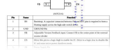
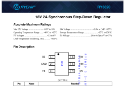
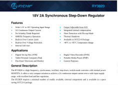
.Found it. The replacement should be a RY3820. I'm still looking for the full datasheet, but this is what I have now (attached).
The chip is relatively easy to get, so I'll order a bunch and give it a try. In the mean time, I'll also look for a more common Western variant...
The chip is relatively easy to get, so I'll order a bunch and give it a try. In the mean time, I'll also look for a more common Western variant...
Attachments
RCinFLA
Solar Wizard
- Joined
- Jun 21, 2020
- Messages
- 3,564
It would be good if you can figure a way to get the existing switchers to power up normally. First thing I would try is putting a good quality output cap on regulators. If that does not work maybe you can eliminate or assist some of the output loads.
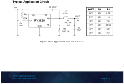
Knowing what the intended output voltage is would be helpful. You can likely figure it out by measuring the resistance of the feedback resistors. This assumes you know the Vfb correctly on the switchers. Both the specs you posted are 0.6v. Many of similar DC-DC converters have 0.8v Vfb.
Next question is if the limit Vin on converters is 18v where does the Vin get generated. I always assumed the switcher with the large PCB secondary coil above the small switchers was the boost for active balancer but maybe it is buck/boost from battery to these three DC-DC.
converters. The three 16v aluminum electrolytics apparently filtering Vin to converters says Vin is less than 16vdc.
Still believe the 4s battery configuration needs a boost to about 15vdc to run the power MOSFET gate drivers reliably for low Rds_ON..
I'm honestly starting to think they put the wrong component on there altogether. RY3820E and RY3820 (and others in that series) are easy to mix up: very similar designation, quite a difference in function. The fact that the problem is apparently solved by swapping with a replacement (i.e., different) component would explain that.
In any case, I've got 100 STI3470 chips coming. I'll order the RY3820 one as well once I hear back from the rep. I'll run some tests on the circuit in isolation, and swap some stuff around.
hwse
Solar Enthusiast
- Joined
- Jan 2, 2021
- Messages
- 585
Once you come up with a workable repair procedure are you willing to sell some of the required bits and bobs so that we do not need to buy a hundred?In any case, I've got 100 STI3470 chips coming. I'll order the RY3820 one as well once I hear back from the rep. I'll run some tests on the circuit in isolation, and swap some stuff around.
Once you come up with a workable repair procedure are you willing to sell some of the required bits and bobs so that we do not need to buy a hundred?
If it works, I'll just send them to whomever asks for the chips; you just have to be able to solder SMDs (or know someone who can).
RCinFLA
Solar Wizard
- Joined
- Jun 21, 2020
- Messages
- 3,564
I assume you are referring to 5.5v Vin limit vs 18v Vin limit.I'm honestly starting to think they put the wrong component on there altogether. RY3820E and RY3820 (and others in that series) are easy to mix up: very similar designation, quite a difference in function. The fact that the problem is apparently solved by swapping with a replacement (i.e., different) component would explain that.
I would be surprised if 5.5v part would survive long enough to load firmware with 13-15v Vin.
Spec for RY3820E is recommending two 22 uF output capacitors. If the two caps I mentioned in the picture are the small chip caps in the lower part of picture, these are pushing the size limit for such a high capacitance. These sized caps, at this large uF, use a very high k dielectric that is very non-linear vs applied DC voltage and have much less capacitance when their use case voltage is a moderate percentage of their rated voltage.
I have seen regulator stability issues when using these super small, high uF ceramic caps.
If this is the case, just piggybacking a good quality, larger cap in 10-22 uF range, on top of existing caps may solve issue.
Last edited:
I assume you are referring to 5.5v Vin limit vs 18v Vin limit.
No, one of them is 500kHz, the other 600kHz - and the resistor choices are somewhat different.
Similar threads
- Replies
- 10
- Views
- 439
- Replies
- 54
- Views
- 2K
- Replies
- 0
- Views
- 144