diy solar

diy solar

FINAL ANSWER on AC out grounding on Growatt SPF3000TL LVM-24P

Thanks for your inputs and advice. Happy you figure out what I should not do.

I am not stacking. It is just 1 inverter and a 48V EG4 battery mainly to support my detached garage with washing machine, dryer, garage opener , a freezer, and a refrigerator. It is just a starter project and may expand with another inverter later.
I trust your judgement and analysis.

The following is what Growatt emailed me. The statement is ambiguous to me. Kind like "Yes and No" answer. Didn't he imply "doesn't do internal dynamic bonding" just in bypass mode?
View attachment 98591
Wow!!! That statement from Growatt about their own product is obviously wrong. If there was no internal bonding you would never see continuity between neutral and ground.

Just to be sure: Once you have it set up check the voltage between neutral and ground both when on battery and in pass-through. (Do it without a load on the output of the inverter. You should see no voltage (or very low voltage) if it has a bond in both cases.

Assuming it has the bond in both cases, you can verify there is only one bond by checking for current on the Equipment Grounding Conductor between the Inverter and the main breaker panel (This time do it while there is a hefty load on the inverter). If there is no current on the ground, there is only one bond.
I trust and acknowledge your expertise!

I am confused which is right - whether the AC Output N-G should be bonded together or not . I thought the old model was said to be bond together and shouldn't.
My guess/understanding with the term "dynamic" bonding internally is: On AC output - Without N-G bond so that when the inverter is not in bypass mode, the inverter's program will bond them together. So my understanding was wrong?

In order to do the voltage check under different scenarios, under program 01- output source priority. The default is most likely solar when I turn on the system. Is there a way I can temporarily setup on Battery or Utility Grid so that I can check the voltages on N-G? Otherwise, I would have to do one or two of those steps at midnight .
 
I am confused which is right - whether the AC Output N-G should be bonded together or not . I thought the old model was said to be bond together and shouldn't.
The old version had no internal bonding but provided a dry contact that was supposed to be used to set up an external bonding relay for generating the bond when on battery power. This never worked very well (Primarily because they gave no instructions on how to do it and so people never did it).

The new version has the bonding relay built-in.

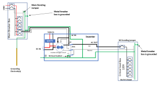
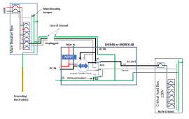
Your set-up will be something like this:

1655271313142.png


My guess/understanding with the term "dynamic" bonding internally is: On AC output - Without N-G bond so that when the inverter is not in bypass mode, the inverter's program will bond them together. So my understanding was wrong?
No that is correct. When the inverter is on battery the output is disconnected from the main breaker panel so the internal bonding relay connects neutral and ground. When the inverter is in passthrough mode, the internal bonding really disconnects the bond and the system uses the bond in the main breaker box feeding the AC in.
 
The old version had no internal bonding but provided a dry contact that was supposed to be used to set up an external bonding relay for generating the bond when on battery power. This never worked very well (Primarily because they gave no instructions on how to do it and so people never did it).

The new version has the bonding relay built-in.

Your set-up will be something like this:

View attachment 98656


No that is correct. When the inverter is on battery the output is disconnected from the main breaker panel so the internal bonding relay connects neutral and ground. When the inverter is in passthrough mode, the internal bonding really disconnects the bond and the system uses the bond in the main breaker box feeding the AC in.
Thank you for the info. and taking the trouble to draw a sketch. That is exactly what my Load box look like.

I looked at Will P's video on the sequence of turning the system on. He turned on Battery first, follow by inverter and then the solar panel. I am using a 10 awg 20 amps extension cord readly to plug into a non- GFCI 20 Amps outlet as the AC input. I believe I need to keep the AC input to the inverter on at all times to have N-G tied to the Main Service panel when the system is in battery or solar mode. Correct?

Another way I think is to add a toggle switch on the Input 20A outlet to keep the N & G feed into the inverter even the Input outlet is toggled off. Correct?
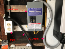
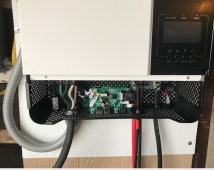
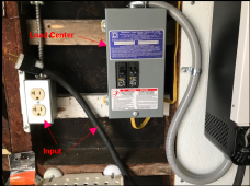
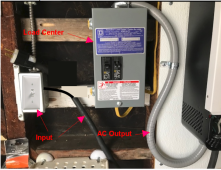
Here are what my AC In & OUT look like.
1655306383967.png
1655306438106.png
 

Attachments

  • 1655306261738.png
    1655306261738.png
    517 KB · Views: 2
I believe I need to keep the AC input to the inverter on at all times to have N-G tied to the Main Service panel when the system is in battery or solar mode. Correct?
Correct
Another way I think is to add a toggle switch on the Input 20A outlet to keep the N & G feed into the inverter even the Input outlet is toggled off. Correct?
Sorry.... I don't understand what you are describing.
 
Correct

Sorry.... I don't understand what you are describing.

What I meant is if AC Input is not wired or not plugging the input extension cord plug into the utility AC input receptacle, that means the inverter is not tied/linked to the Main Service Panel ( since there is no N & G wire linking the inverter to the Main Service panel).
Adding a switch to the utility receptacle:
Because a switch is only for toggling the Live wire on the utility receptacle, if the Input plug remains on the utility AC receptacle regardless of whether the switch is turned on or off, the N & G from the utility receptacle or Main Service Panel are still connected to the inverter. That would keep the inverter N & G tied to the Service Panel 24/7. Agree?
 
Last edited:
OK.... I think I understand now. I was incorrect in my previous answer.

It turns out you don't need to worry about the NG-Bond when unplugged
Case one: The inverter is plugged in: Everything is OK because in pass-through mode the main panel supplies the N-G bond and all other times the Inverter provides the N-G bond.

Case two: The inverter is not plugged in: Everything is OK because the inverter will never be in pass-through mode and the inverter will always have the N-G bond enabled.

However, as you point out, the system will be floating because of the loss of the ground connection when unplugged.

1655314106444.png

The loss of neutral and hot are not an issue, but the loss of ground can be. An ungrounded (Floating) system is technically ok (but may not be to code). However, a floating system is more likely to suffer damage from static or induced charges so I always try to ground the system.

Your suggestion is to put a switch on the hot so you can leave it plugged in and use the switch to turn it off when you need to. This works, but then I have to ask "why have the plug at all?" Why not replace the plug with a switch and hard wire the inverter into the box?

1655315656700.png


Another potential issue to point out:

Edit: Corrected the plug rating.
The picture shows a 15A plug and a 20A receptacle, but the inverter is a 3000W inverter. A 3000W inverter can draw over 25A when in pass-through and charging the battery. The proper setup would have a 30A circuit with 10AWG wires all the way back to the main breaker box and a 30A breaker at the box. If you do this, you need to find a high current switch (The typical light switch is not rated for 30A)
 
I have mine on a plug. During possible thunderstorms I have a 4 feet fiscal separation from the grid. My Schneider 6848 I use a 4 wire range cord and receptacle.
 
OK.... I think I understand now. I was incorrect in my previous answer.

It turns out you don't need to worry about the NG-Bond when unplugged
Case one: The inverter is plugged in: Everything is OK because in pass-through mode the main panel supplies the N-G bond and all other times the Inverter provides the N-G bond.

Case two: The inverter is not plugged in: Everything is OK because the inverter will never be in pass-through mode and the inverter will always have the N-G bond enabled.

However, as you point out, the system will be floating because of the loss of the ground connection when unplugged.

View attachment 98702

The loss of neutral and hot are not an issue, but the loss of ground can be. An ungrounded (Floating) system is technically ok (but may not be to code). However, a floating system is more likely to suffer damage from static or induced charges so I always try to ground the system.

Your suggestion is to put a switch on the hot so you can leave it plugged in and use the switch to turn it off when you need to. This works, but then I have to ask "why have the plug at all?" Why not replace the plug with a switch and hard wire the inverter into the box?

View attachment 98706


Another potential issue to point out:

Edit: Corrected the plug rating.
The picture shows a 15A plug and a 20A receptacle, but the inverter is a 3000W inverter. A 3000W inverter can draw over 25A when in pass-through and charging the battery. The proper setup would have a 30A circuit with 10AWG wires all the way back to the main breaker box and a 30A breaker at the box. If you do this, you need to find a high current switch (The typical light switch is not rated for 30A)
Thanks for reading what I put forth.

The extension cord with a plug I used is custom made with $13 Leviton 20A plug (not 15 A) and 10 AWG strand wire ( the plug recommended using only stranded wire). The idea using extension cord came from Will P's video. The inverter has recommended using 10 awg wire for the input. It is hard to buy a short 10 awg wire with a 20A plug. All the ready made short 10 awg extension cords all came with 15 A plug so I decied to make my own. I then realized if I didn't have the plug connected I would have N-G tie back to Service panel issue and decided to use a toggle switch to control the Live wire instead and ask you what you think since I also have the plug made.

I fully agreed with you just using a switch without the plug. But the issue is 10 AWG I am using from the inverter is difficult to wire to a 20 A switch. As I am not running large load, I predict I won't draw over 20A for now . Had it exceeded, the supply breaker would trip and then I would upgrade the input amperage.
 
Back
Top