Actually thats is a pic from when I had the charger hooked up. its hard to tell but its hooked to the negative lead from the charger and the positive is hooked to the positive terminal. Its a blue negative wire and a brown positive wire both covered in a black insulation leading off camera.Can't tell for sure, but it looks like you have the negative output from the BMS hooked the Positive terminal of the battery? If so, why?
If not, where is the black wire from the positive terminal going?


You are using an out of date browser. It may not display this or other websites correctly.
You should upgrade or use an alternative browser.
You should upgrade or use an alternative browser.
Finally found a LiFePO4 BMS with Low-temp Charging Protection
- Thread starter Will Prowse
- Start date
Sgt Raven
Solar Addict
- Joined
- Feb 17, 2020
- Messages
- 1,079
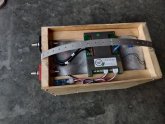
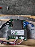
Blue wires to the Neg terminal along with the small black BMS wire. Then the small white BMS wires start on the Pos of that cell and then to each Pos in line, the little red wire goes to the last/main Pos terminal. Big Black wires from the BMS are the Neg terminal output from the Battery. The last Pos terminal on the cells is the Pos terminal for the battery. Your load is hooked to that Pos terminal and the big Black wires from the BMS. Check and make sure you have the all those hooked up right. I'm confused by your pic and the other wires hooked to the pos terminal.What am I doing wrong?
I had this battery hooked up in paralel for three weeks and they all were at 3.292 4cell 150ah lifepo4.
Hooked up the bms per wills video and I get all kinds of weird things. hooking up my charger makes no difference to the readings at all. if anyone can be of help and maybe tell from the pictures what I did wrong it would be much appreciated.
View attachment 12938

Sgt Raven
Solar Addict
- Joined
- Feb 17, 2020
- Messages
- 1,079
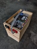
Take your DMM and check each cell between the Pos and Neg of each and see what their cell voltages are. You can do this while they're all hooked together. Then you have the DMM on the 1st neg and go up the battery to each Pos and the readout should add each cell into the total Like 3.2V, 6.4V, 9.6V and 12.8V just pulling the numbers out as a example. Start with the simple stuff and check your work.Actually thats is a pic from when I had the charger hooked up. its hard to tell but its hooked to the negative lead from the charger and the positive is hooked to the positive terminal. Its a blue negative wire and a brown positive wire both covered in a black insulation leading off camera.
yeah as i said above the extra wires are the charger/power supply. Looks like I have it connected the same way you have.Blue wires to the Neg terminal along with the small black BMS wire. Then the small white BMS wires start on the Pos of that cell and then to each Pos in line, the little red wire goes to the last/main Pos terminal. Big Black wires from the BMS are the Neg terminal output from the Battery. The last Pos terminal on the cells is the Pos terminal for the battery. Your load is hooked to that Pos terminal and the big Black wires from the BMS. Check and make sure you have the all those hooked up right. I'm confused by your pic and the other wires hooked to the pos terminal.
View attachment 12947
They test at 3.292, 3.284, 3.292, and 3.286. After screwing around with the charger and stuff. they werre all at 3.292 to start with.Take your DMM and check each cell between the Pos and Neg of each and see what their cell voltages are. You can do this while they're all hooked together. Then you have the DMM on the 1st neg and go up the battery to each Pos and the readout should add each cell into the total Like 3.2V, 6.4V, 9.6V and 12.8V just pulling the numbers out as a example. Start with the simple stuff and check your work.
Sgt Raven
Solar Addict
- Joined
- Feb 17, 2020
- Messages
- 1,079
Start simple and double check each connection. Also if you unplug the small BMS wire connector from the BMS and use the Pos probe of your DMM. Your voltages should add up the same as doing it up the cells of the battery. See if each small wire is sending the right info to the BMS. I know trying to explain it as best I can. But the 4 Pos BMS wires should read the same as starting on the Neg and 1st Pos and checking the cells in order. Does this make sense?yeah as i said above the extra wires are the charger/power supply. Looks like I have it connected the same way you have.
Sgt Raven
Solar Addict
- Joined
- Feb 17, 2020
- Messages
- 1,079
We now know where they are and it's not the cells. Now check the BMS end of the sense wires and make sure what you have going into the BMS as signals.They test at 3.292, 3.284, 3.292, and 3.286. After screwing around with the charger and stuff. they werre all at 3.292 to start with.
Sgt Raven
Solar Addict
- Joined
- Feb 17, 2020
- Messages
- 1,079
I would look close at the sense wire for cell #3. Maybe the ring terminal isn't making good contact with the wire or cell terminal. Just a SWAG, but I think the BMS subtracts the reading from the cells before it in line to figure out the next cell voltage. I say this because it is only seeing the Pos reading after the first cell Neg. If it is not getting a good signal from one Pos cell connection, it may throw off all the rest of the cells readout..They test at 3.292, 3.284, 3.292, and 3.286. After screwing around with the charger and stuff. they werre all at 3.292 to start with.
Start simple and double check each connection. Also if you unplug the small BMS wire connector from the BMS and use the Pos probe of your DMM. Your voltages should add up the same as doing it up the cells of the battery. See if each small wire is sending the right info to the BMS. I know trying to explain it as best I can. But the 4 Pos BMS wires should read the same as starting on the Neg and 1st Pos and checking the cells in order. Does this make sense?
Ok so maybe some bad sense wires then? Ill check this out in the morning. Thanks I hadn't thought of that.We now know where they are and it's not the cells. Now check the BMS end of the sense wires and make sure what you have going into the BMS as signals.
Sgt Raven
Solar Addict
- Joined
- Feb 17, 2020
- Messages
- 1,079
Sure thing, this will give you a starting place before we think of a bad BMS. Rule out all the simple stuff first At the same time check to make sure they're all connected in the proper order..Ok so maybe some bad sense wires then? Ill check this out in the morning. Thanks I hadn't thought of that.
Sgt Raven
Solar Addict
- Joined
- Feb 17, 2020
- Messages
- 1,079
On my 120A S-BMS it had 3 10AWG wires. The 3 of them tinned just fit in a 4AWG lug. Someone else switched his to 8AWG and without being tinned, they fit in a 4AWG lug, too. I had to take a file to 1 of the 6 wires and knock a couple of high spots off of it. Before you crimp it, make sure you're happy how the wires are going to lay. If I was to do it again, I would take more care in that asspect. Maybe a couple of small wire ties when prepping to install the fitting. To keep the wires lined up the way you want. At some point I will probably cut one of the lugs off and change to a 4AWG butt sleeve to extend the wires with a single 4AWG cable. At the same time try and plan where you're going to place the BMS. That could affect how you finish off the group of wires. Do you need to lengthen the blue ones to the Neg terminal on the battery and the black ones to the Negative Buss for the circuit. These would work on my setup. I used the lugs, because I didn't have the butt connectors on hand. But I havebn't finalized my setup, yet and may change it before I'm done.What size are the included wires to negative/load? Or rather, what's the appropriate connector size to fit 3 of those wires?
https://www.amazon.com/gp/product/B01MSJGP1Q/ref=ppx_yo_dt_b_asin_title_o05_s00?ie=UTF8&psc=1
https://www.amazon.com/gp/product/B00O5BATJ2/ref=ppx_yo_dt_b_asin_title_o02_s00?ie=UTF8&psc=1
Ok I traced those wires last night about a dozen times to make sure they were going to the correct cell. I dont know why except maybe I was tired from working all day. But I had two of the wires swapped places. Found it when I was reading the voltages on the sensor wire plug. even then it took me a minute to figure out. I mean the readings I got could only mean that the wires were on the wrong cell but it still looked like they were correct. So I took them all off and very carefully put them back on one by one. Fixed it.
Thanks so much guys!
App works great too. Now to fix my charger/power supply. The fan is rubbing on something and making a racket. Gonna have to open it up and check it out.
Thanks so much guys!
App works great too. Now to fix my charger/power supply. The fan is rubbing on something and making a racket. Gonna have to open it up and check it out.
Sgt Raven
Solar Addict
- Joined
- Feb 17, 2020
- Messages
- 1,079
With the readings on the BMS, I was pretty sure either wires out of order or a bad connection on one of them. It was what seemed the logical thing.Ok I traced those wires last night about a dozen times to make sure they were going to the correct cell. I dont know why except maybe I was tired from working all day. But I had two of the wires swapped places. Found it when I was reading the voltages on the sensor wire plug. even then it took me a minute to figure out. I mean the readings I got could only mean that the wires were on the wrong cell but it still looked like they were correct. So I took them all off and very carefully put them back on one by one. Fixed it.
Thanks so much guys!
App works great too. Now to fix my charger/power supply. The fan is rubbing on something and making a racket. Gonna have to open it up and check it out.
Sgt Raven
Solar Addict
- Joined
- Feb 17, 2020
- Messages
- 1,079
I had to do the same thing after I knew everything worked good. I took it apart and sleeved the Sense wires and Bluetooth wires.With the readings on the BMS, I was pretty sure either wires out of order or a bad connection on one of them. It was what seemed the logical thing.
Except I used the continuity tester function to ID each of the white wires.
I wanted to make it look a bit prettier than a bunch of loose wires.

Last edited:
ianlloyd100
New Member
- Joined
- Dec 17, 2019
- Messages
- 43
So I have this BMS (the 100A version) all hooked up and running nicely. Apart from the fact that the single cell full limit is set at 3.4V I cannot find anywhere to change it in the settings page. My Cells are the 190Ah Blue cells from BLS, Bluetooth is working well, I can change a whole load of settings, but cannot get the single cell max volts above 3.4.. Any Ideas?....
Sgt Raven
Solar Addict
- Joined
- Feb 17, 2020
- Messages
- 1,079
Which version # of the App are you running? I think know how to change it in V3.1.1001. You can find this in About XiaoxiangSo I have this BMS (the 100A version) all hooked up and running nicely. Apart from the fact that the single cell full limit is set at 3.4V I cannot find anywhere to change it in the settings page. My Cells are the 190Ah Blue cells from BLS, Bluetooth is working well, I can change a whole load of settings, but cannot get the single cell max volts above 3.4.. Any Ideas?....
This is my First attempt at posting. I have watched numerous videos concerning various methods of hooking up LiFePO4 batteries. I have just purchased (4) of the below listed battery packs from Ebay. There are a total of 128 cells in the purchase. Each cell is 3.6 volts and 40Ah. I have a 48 volt system with a Magnum MS4448PAE inverter. My old AGM batteries did not survive the past Winter. They were 14 years old... I see in Will's video on top balancing that he hooks All of his batteries in Parallel, to do the balancing act. My Question is? Why not leave them that way? I would like to build my battery pack after bottom and top balancing, By hooking 8 cells in Parallel creating one battery (Set) of 3.6 volts and 320Ah. Then connecting 16 of these (Sets) in series to achieve my 48+ volt required battery pack. What problems do you foresee? I anticipate adding a BMS to the system, and it is my understanding I would be able to operate with ONE BMS that would monitor the 16 battery (Sets). Still studying the Overkill BMS and awaiting the release of the New Chargery with all of the upgrades that have been suggested. Thank you in advance for all of your experience.. If I have posted this in the wrong place, or if it would receive more responses somewhere else please let me know or move it if you can. Thanks..You are correct the BMS is not going to do it- I wrote up what I know about balancing here:
 | lithium ion battery cells 160ah LFP Etrust Brand (Solar Backup) | eBay The system demonstration was operational only for a couple of months. ebay.us |
Sgt Raven
Solar Addict
- Joined
- Feb 17, 2020
- Messages
- 1,079
Yes 8P16S is one version of a 48V battery you could build. There is some questions or disputes on what the maximum number of cells paralleled you should use and the problems that arise from the different combinations. I'll let someone with more knowledge on the subject answer your questions about that. Just posting so you see someone is reading your post.This is my First attempt at posting. I have watched numerous videos concerning various methods of hooking up LiFePO4 batteries. I have just purchased (4) of the below listed battery packs from Ebay. There are a total of 128 cells in the purchase. Each cell is 3.6 volts and 40Ah. I have a 48 volt system with a Magnum MS4448PAE inverter. My old AGM batteries did not survive the past Winter. They were 14 years old... I see in Will's video on top balancing that he hooks All of his batteries in Parallel, to do the balancing act. My Question is? Why not leave them that way? I would like to build my battery pack after bottom and top balancing, By hooking 8 cells in Parallel creating one battery (Set) of 3.6 volts and 320Ah. Then connecting 16 of these (Sets) in series to achieve my 48+ volt required battery pack. What problems do you foresee? I anticipate adding a BMS to the system, and it is my understanding I would be able to operate with ONE BMS that would monitor the 16 battery (Sets). Still studying the Overkill BMS and awaiting the release of the New Chargery with all of the upgrades that have been suggested. Thank you in advance for all of your experience.. If I have posted this in the wrong place, or if it would receive more responses somewhere else please let me know or move it if you can. Thanks..
lithium ion battery cells 160ah LFP Etrust Brand (Solar Backup) | eBay
The system demonstration was operational only for a couple of months.
ebay.us
Sgt Raven
Solar Addict
- Joined
- Feb 17, 2020
- Messages
- 1,079
In my App version you go to Parameter View and the very top is Cell voltage. Tap on it and a window opens up. Set the voltage that you want and confirm it. It is changed under Parameter View, not Parameter Setting on my version of the App. Parameter settings crashes my version.So I have this BMS (the 100A version) all hooked up and running nicely. Apart from the fact that the single cell full limit is set at 3.4V I cannot find anywhere to change it in the settings page. My Cells are the 190Ah Blue cells from BLS, Bluetooth is working well, I can change a whole load of settings, but cannot get the single cell max volts above 3.4.. Any Ideas?....
ianlloyd100
New Member
- Joined
- Dec 17, 2019
- Messages
- 43
So, choosing the "about Xiaoxiang" only takes me to the Bluetooth settings, and there is no info annoy the app there. Looking at the info for the app icon, it looks like version is 2.0.1006. My parameter view, shows lots of info, but does not allow any changes. This has to be done in parameter settings... This is the setting I want to change..Which version # of the App are you running? I think know how to change it in V3.1.1001. You can find this in About Xiaoxiang

ianlloyd100
New Member
- Joined
- Dec 17, 2019
- Messages
- 43
Does anyone have a later version of the software for android, I am using the one, Will has on his site. Its the enterprise version, so changes can be made. I found the one in the play store, but that is extremely limited, and does not allow any changes..
Sgt Raven
Solar Addict
- Joined
- Feb 17, 2020
- Messages
- 1,079
use the one here.Does anyone have a later version of the software for android, I am using the one, Will has on his site. Its the enterprise version, so changes can be made. I found the one in the play store, but that is extremely limited, and does not allow any changes..
https://github.com/FurTrader/OverkillSolarBMS
Similar threads
- Replies
- 4
- Views
- 352
- Replies
- 3
- Views
- 325
- Replies
- 8
- Views
- 219
- Replies
- 0
- Views
- 282