diy solar

diy solar

fuse question

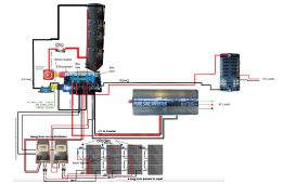
If you have a 250A fuse leaving the battery… why do you want a 375A feeding the inverter…
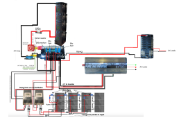
I don't really know tbh. I've a pretty thin grasp of this stuff so I mostly just do whatever my most recent advisor (my electrician roommate) tells me. I've updated the diagram w/ 200a bolt on fuse to the inverter cuz he said that's what 4/0 wire wants. New question tho, I don't think I can get 4/0 wire to my battery bank cuz they use these Anderson sb175 connectors which only accommodate up to 0awg. I've emailed the company about it. Can you think of a work around?
 

Attachments

  • newdiagram9.png
    newdiagram9.png
    307.1 KB · Views: 6
  • 12V-OWL.pdf
    745.5 KB · Views: 2
Which equipment do you need specs for? The wire sizes are listed.
Sorry. On my phone- the diagram apparently hadn’t loaded when I replied. I thought you didn’t have any specs so I didn’t know what to think.
Nevertheless other people have answered.
 
Last edited:
Your roommate doesn't have a clue. Don't follow that advice. Do not use glass fuses with soldered leads. Learn to use a voltage drop table. Use a 2000W inverter or consider going to 24 volt system. Speculation: 3000w inverter needs 300 amp fuse. 4/0 marine grade cable needs >400 ampere fuse as catastrophic fuse at the positive battery-bank terminal.
"speculation" because we need length of cables, as well as maximum amperes through that cable, and the insulation grade of that cable, to even come close to knowing what you need. It would help to know what you plan for the battery-bank.
 
o not use glass fuses with soldered leads. Learn to use a voltage drop table. Use a 2000W inverter or consider going to 24 volt system. Speculation: 3000w inver
i have the batteries .pdf attached above. new problem: can't do a 24v system w/ these batteries (bullshit, but i'd probs incur substantial restocking and shipping fees if i returned them / i'd prefer to avoid an uphill battle fighting these fees if possible) and it seems i can't connect anything beyond 0awg to the battery bank because they use anderson connector sb175 which doesn't accommodate larger wires. i've emailed them asking for a work around and haven't heard back yet.
 
Quickly reading through this thread, my first impression is slow down and step back. Approach your system design deliberately, forget the specific question of fuse size, for now, and focus on understanding how the pieces of your system fit together, what the role of a fuse is, and the basic theory of how to size them right in general. Then come back to the specific questions more prepared and informed. Its natural to want to go straight to the questions of implementation, but a basic grasp of the theory goes along way to helping you make sound and informed design decisions.

This video might be an okay place to start:

Or this resource:
 
I'm still not sure how you are configuring battery bank.
I have 3 12 volt batteries connected in parallel for 600ah @ 12 volts. I use BusBars on positive and negative. Each battery is wired to Busbar.
Battery#1 -> 250A fuse -> 1/0 cable -> Positive BusBar#1. Same with Battery#2 & Battery#3. Then, Positive BusBar#1 -> 400A fuse -> 4/0 cable -> 3000W inverter. https://www.bluesea.com/products/2107/PowerBar_600A_BusBar_-_Eight_3_8in-16_Studs__
(or use positive BusBar#2 then other devices,)
Same general idea for Negative side without fuses.
 
it's 4 170ah batts in parallel for 680ah at 12v in my case.
I'm still not sure how you are configuring battery bank.
I have 3 12 volt batteries connected in parallel for 600ah @ 12 volts. I use BusBars on positive and negative. Each battery is wired to Busbar.
Battery#1 -> 250A fuse -> 1/0 cable -> Positive BusBar#1. Same with Battery#2 & Battery#3. Then, Positive BusBar#1 -> 400A fuse -> 4/0 cable -> 3000W inverter. https://www.bluesea.com/products/2107/PowerBar_600A_BusBar_-_Eight_3_8in-16_Studs__
(or use positive BusBar#2 then other devices,)
Same general idea for Negative side without fuses.
 
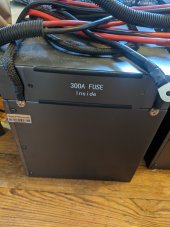
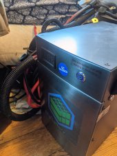
you know, how necessary are some of these fuses leading to the battery bank given that these batteries actually have 300a fuses incorporated into each one?

PXL_20211109_202854448.jpg

PXL_20211109_203738251.jpg

PXL_20211109_205735938.jpg

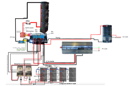
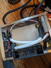
also, i guess for the parallel connections i could build something like this:


Attachments

  • newdiagram9.png
    newdiagram9.png
    307.1 KB · Views: 3
also, do i need to run the 4/0 cable between the batteries or just leading up to them. say ending at such a box:

 
Back
Top