diy solar

diy solar

Got a mess

kdsmith

New Member
Joined
Jan 2, 2024
Messages
15
Location
US/SC
We had a cable going from positive on first battery to the inverter to get so hot it was smoking and melting so we took load off and shut off inverter. We had a 1500 watt heater running which we've done a few times before adding a 2nd battery. So I guess a heater is a no go with this setup. Other than replacing this wire, a busbar has been recommended and what else to improve? Which busbar and where/ how to hook that up?

Equipment: 4x100 watt panels in parallel. 2000 watt inverter, 30 amp Wanderer controller. all Renogy.
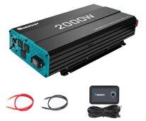
2 AGM Weize batteries in parallel, not renogy. Theres a 300 amp ANL fuse between inverter and battery which someone recomended a lower fuse.The controller, inverter and other battery all on one battery post. Cables/wires all came in a bundle from Renogy except the set pairing both (1/0 AWG) batteries together.Screenshot_20231231_121847_Amazon Shopping.jpg
 
Last edited:
Hi KD. Some important details missing here, like the battery voltage, and the size of wire going from the batteries to the inverter. A bit more of a list of details, even inverter model would help.

For a general idea, if running 1500 watts on a 12v system, you would divide the 1500 watts by 12 to get the amperage. That is a lot of amperage, and would require a pretty beefy wire. Generally plan for some overhead in everything too, as running anything maxed out is not ideal.

There are some smart peeps on here that can provide more detail with some better specs, but the math will give you a pretty good idea. Sounds like your interconnects are barely big enough for 1500 watts, so if the wires from inverter to batteries are smaller, that's the trouble.
 
It could be a bad connection I would clean and tighten all connections and also verify that the cables are capable of handling at least 200 amps
 
Do you have an amp clamp meter probe to measure the actual current on your wire? (just to get some rough idea of the current it was flowing)

Have you checked the inverter documentation to see if they publish a max amps draw spec?

Have you had a chance to review the NEC ampacity chart?

Are there any labels on the wire to identify its specs?

According to NEC ampacity chart, 170a is the max @194° F...

The breaker / fuse should be sized to protect the wire from overcurrent (insulation meltdown), and breaker / fuse should be sized 20% smaller than the wire's max ampacity rating.
 
Hi KD. Some important details missing here, like the battery voltage, and the size of wire going from the batteries to the inverter. A bit more of a list of details, even inverter model would help.

For a general idea, if running 1500 watts on a 12v system, you would divide the 1500 watts by 12 to get the amperage. That is a lot of amperage, and would require a pretty beefy wire. Generally plan for some overhead in everything too, as running anything maxed out is not ideal.

There are some smart peeps on here that can provide more detail with some better specs, but the math will give you a pretty good idea. Sounds like your interconnects are barely big enough for 1500 watts, so if the wires from inverter to batteries are smaller, that's the trouble.
So I'm new and tried to provide what I knew. The wire was provided by Renogy in their bundle so i assumed you used what they sold with kit which was 1/0AWG. There's 2 12V 100AH Weize AGM batteries,
 
So I'm new and tried to provide what I knew. The wire was provided by Renogy in their bundle so i assumed you used what they sold with kit which was 1/0AWG. There's 2 12V 100AH Weize AGM batteries,

I have seen some vendors who sell bundles with cables, send the wrong cables. It is always up to the installer tech to gut-check all the components and confirm installation will be safe before signing off on it.

But don't worry, that's why we're here to help you. And at the end of the day you'll be all set :)
 
After rereading the post, it looks like it is 12V. A 1500W load at 12V would require inverter supply wire ampacity of 174A. That's calculated as 1500/12/inverter efficiency, so assuming 90%, 1500/12/.9 = 139A. NEC requires wire of 125% of that ampacity, so 139 * 1.25 = 174A. If a free air application, then #1 THHN would be required assuming 75C terminations. If not free air, then 2/0 would be required.

Using the same assumptions but for the full load inverter capacity of 2000W, the inverter wiring would need an ampacity of 231A, or 1/0 and 4/0, respectively.

This may be a case of loose/bad connections since you've run the heater before without problems.

I would not be comfortable with the existing wire gauges though and would seriously consider upgrading them.
 
So I'm new and tried to provide what I knew. The wire was provided by Renogy in their bundle so i assumed you used what they sold with kit which was 1/0AWG. There's 2 12V 100AH Weize AGM batteries,
Someone can check my math, but I was recently looking at sizing wire for my 12V system.

Even 1/0 could be too low for a 1500W draw, right?

If you assume a poor case scenario: 1500W / .85 (efficiency) / 10.5V (low battery or voltage drop) = ~168 amps

A poster in my thread had pointed out that you need to take efficiency and potential voltage drop into consideration, so I just roughed in some bad-case-scenario numbers there.

I guess if you had the correct 1/0 wire, you might be okay, but I personally would want to oversize with a safety margin. In my case I ended up going with 4/0 cable (expensive and thick!) but better safe than sorry. At a full 2000W draw on that inverter, no way would I feel safe with 1/0.
 
Hi KD. Some important details missing here, like the battery voltage, and the size of wire going from the batteries to the inverter. A bit more of a list of details, even inverter model would help.

For a general idea, if running 1500 watts on a 12v system, you would divide the 1500 watts by 12 to get the amperage. That is a lot of amperage, and would require a pretty beefy wire. Generally plan for some overhead in everything too, as running anything maxed out is not ideal.

There are some smart peeps on here that can provide more detail with some better specs, but the math will give you a pretty good idea. Sounds like your interconnects are barely big enough for 1500 watts, so if the wires from inverter to batteries are smaller, that's the trouble.
 
Someone can check my math, but I was recently looking at sizing wire for my 12V system.

Even 1/0 could be too low for a 1500W draw, right?

If you assume a poor case scenario: 1500W / .85 (efficiency) / 10.5V (low battery or voltage drop) = ~168 amps

A poster in my thread had pointed out that you need to take efficiency and potential voltage drop into consideration, so I just roughed in some bad-case-scenario numbers there.

I guess if you had the correct 1/0 wire, you might be okay, but I personally would want to oversize with a safety margin. In my case I ended up going with 4/0 cable (expensive and thick!) but better safe than sorry. At a full 2000W draw on that inverter, no way would I feel safe with 1/0.

Yeah, and oversize cable can lead to better performance! Especially at lower battery voltage when the inverter is trying to pull more amps for the same watts output...
 
Lots of info overload lol. OK to start, we can't use the wire that Renogy sent in this bundle and the ANL fuse is too big. All this started (going solar) to run a laser engraver and we havent even gotten to that part! What about a busbar or addressing all of this connected to the positive terminal?
 
1) Generally we advise not to exceed 250A draw from a battery system,, that put 12V capped to 3000W max. 2000W @ 12V is 133A UNCORRECTED.
2) Wire Length + devices in-line (shunt, switch etc) all add residence & losses. This also has to be acounted for.
3) leaving extra space for Surge Draws etc is always prudent.

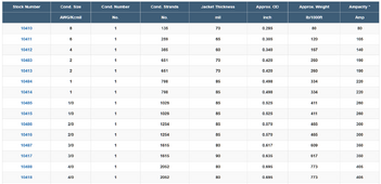
Using the chart below, by SouthWire Co related to their Ultra Fine Wire Welding Cable (some of the best out there) shows that 2-AWG is "sufficient" but that 1-AWG would be optimal for that setup.

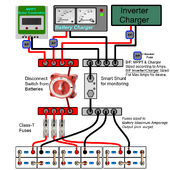
Below the table is an A-Typical generic "component" Solar System layout, showing paralleled batteries, using busbar, shunt, switch etc... It also indicated where fuses/breakers should be located. NOTE that is dos not show that for Solar Power In which should also be Fused or through Breaker.
Excelene Wire Table.PNG

NOTE with 12/24 V system, you can also use MRBF Fuses for the batteries making it far simpler and less $.
Parallel System-setup PNG.png
 
It seems like there is an increasing number of cable overheating/insulation melting/wires smoking reports on the forum. The NEC ampacity charts may seem overly conservative, but it is all about safety. I've used them (been required to) for 30 years and have never had a conductor burn or catch fire because it was undersized per the code.

Another warning sign I see on the forum is arguments that conductor length is short, so smaller conductors can be used based solely on voltage drop. Nowhere does the NEC allow reduction in conductor size from the ampacity tables because of length or voltage drop. Conductors can only be increased in size to reduce voltage drop.
 
Another warning sign I see on the forum is arguments that conductor length is short, so smaller conductors can be used based solely on voltage drop. Nowhere does the NEC allow reduction in conductor size from the ampacity tables because of length or voltage drop. Conductors can only be increased in size to reduce voltage drop.
As someone relatively new to solar, I see this a lot, which adds to the confusion. There must certainly be some degree of truth to this though, right?

One thing that I found confusing as a new user was the wide variety of wire and insulation types and trying to compare that to the NEC charts... on top of even figuring out what kind of wire material/construction and insulation type on wire you're trying to buy!

I've read some of the material for beginners in the "Resources" section, including the very detailed guide on wire ampacity, but it really seems like that part is just overlooked. As a new person in the space, it can be hard to wrap your head around it.
 
Can anyone recommend a 4/0 wire? Everything I have came from Renogy Amazon store. Also do I need 250 ANL rather than the 300? And to busbar or not?
 
Can anyone recommend a 4/0 wire? Everything I have came from Renogy Amazon store. Also do I need 250 ANL rather than the 300? And to busbar or not?
If you're looking for premade cables, I personally opted for WindyNation, which is what I believe is recommended on Will's page.

They're definitely good quality cables. You can get them on Amazon or their site. I ordered most recently from their site, and they got to me in two days flat with free shipping, which was great.
 
So I'm new and tried to provide what I knew. The wire was provided by Renogy in their bundle so i assumed you used what they sold with kit which was 1/0AWG. There's 2 12V 100AH Weize AGM batteries,

OP, is it correct that you're running a 1,500 watt heater on 2 x 100ah 12V batteries? That heater will consume about 125 amps per hour. AGM batteries don't like being discharged more than 80% (I'd stick to 50%) so those batteries have a usable capacity of 100 - 160 ah meaning they have the capacity to run that heater for about 45 - 75 minutes before needing a recharge.

Is this what you had in mind? Tell me if I'm missing something.
 
Last edited:
OP, is it correct that you're running a 1,500 watt heater on 2 x 100ah 12V batteries? That heater will consume about 125 amps per hour. AGM batteries don't like being discharged more than 80% (I'd stick to 50%) so those batteries have a usable capacity of 100 - 160 ah meaning they have the capacity to run that heater for about 45 - 75 minutes before needing a recharge.

Is this what you had in mind? Tell me if I'm missing something.
Yes we were running a heater but as far as time, it is in my building, not house. We were just uncrating a piece of equipment so plan would not have even been 45 to 75 mins. Now the whole plan of this was to run a laser engraver and these batteries may not be feasible for that either.
 
Yes we were running a heater but as far as time, it is in my building, not house. We were just uncrating a piece of equipment so plan would not have even been 45 to 75 mins. Now the whole plan of this was to run a laser engraver and these batteries may not be feasible for that either.
Do you know how many watts it takes to operate the laser engraver? I don't know a thing about them but the google suggested less than 150 watts so consumption is dramatically less than the heater and you'd probably be able to run the engraver for a decent amount of time.

Electric heat is a huge draw. Are you planning on using this for heat on a regular basis?

Feel free to walk us back and tell us what you want to do with this set-up. Operate a laser engraver at a craft show 8 hours a day? Keep your van warm? when it's 30 degrees outside?
 
Back
Top