diy solar

diy solar

Gotion 340Ah Cells

Reigate

New Member
Joined
Feb 1, 2020
Messages
17
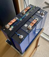
I recently purchase four Gotion 340Ah LFP cells and because of scepticism on the forum about their true capacity, decided to fully test all four using an EBC-A20. Please refer to the attached files for complete results but simply, the tested normalised capacities were as follows:
Cell 1: 366Ah
Cell 2: 365Ah
Cell 3: 364Ah
Cell 4: 367Ah

Overall, very happy with the purchase.

Notes:
1. The EBC-A20 can only discharge at 20 amps (0.06C) rather than at 0.2C so the results are probably, a little optimistic.
2. The EBC-A20 calculates the capacity using average voltage rather than the industry accepted testing value of 3.2 so the above capacities have been normalised.
3. The EBC-A20 was voltage calibrated at 2.50 and 3.65 volts and monitored with a 22000 count DMM. Voltage difference between the EBC-A20 and DMM throughout testing was a maximum of 10 mV.
4. The alligator clips on the end of the EBC-A20 leads were replaced with M6 ring terminals to ensure a better battery connection.
5. The cells were purchased from www.tewaycell.com and came with four, high quality, flexible copper bus bars which are sized to fit the wider Gotion cells as standard ones are too small.
6. The Simplified Data spreadsheets have had the initial and final charge data removed which has caused a very minor error in the data presented at the bottom of the Combined Curve. Refer to the Complete Data spreadsheets for accurate discharge energy values.
 

Attachments

  • 340Ah Data.zip
    663.6 KB · Views: 6
That's impressive!

What manufacture date or QR code range are your cells? - what did the test report show for capacity? Mine showed 340-344Ah *Edit Just saw it was (1/Jun/2023)

I bought mine from GobelPower and they sent cells over 14 months old. :cautious: (22/Aug/2022)

I'll do a capacity test when mine are balanced, but did get 1002.6Ah from 1020Ah total (340 x 3) initially whilst they were unbalanced, using a SmartShunt to check.

What charge rate are you able to do? I can do 0.3C with a genny, but some cells act weird in absorption, so I've had to lower it for now.

I have not finished testing properly, or managed to balance them all properly yet, still winter here and topped up on the genny, ( they were initially within 30mv at 3.45v so I left them together on the inverter + SCC's), I only have the thin solid busbars though. But I have two cells that seem to run up to a high voltage early if I charge above 0.2C, the JK BMS's balances the runners down initially, then when the others come up close to my 3.5v target and the absorption current drops, the two runners switch to snails and show a lower voltage and the BMS starts balancing them up! Either dodgy connections or cells, but the IR tested ok and test report seemed to roughly concur. I've set the charge algorithm to charge them more gently in absorption to avoid the runners being balanced down, but weird for now until they are balanced and I can test properly.

Thanks for the tip on flexible busbars, I'll see if they can supply them separately, as I couldn't find them to fit the fatter 340Ah cells before.
 
Last edited:
That's impressive!

What manufacture date or QR code range are your cells? - what did the test report show for capacity? Mine showed 340-344Ah *Edit Just saw it was (1/Jun/2023)

I bought mine from GobelPower and they sent cells over 14 months old. :cautious: (22/Aug/2022)

I'll do a capacity test when mine are balanced, but did get 1002.6Ah from 1020Ah total (340 x 3) initially whilst they were unbalanced, using a SmartShunt to check.

What charge rate are you able to do? I can do 0.3C with a genny, but some cells act weird in absorption, so I've had to lower it for now.

I have not finished testing properly, or managed to balance them all properly yet, still winter here and topped up on the genny, ( they were initially within 30mv at 3.45v so I left them together on the inverter + SCC's), I only have the thin solid busbars though. But I have two cells that seem to run up to a high voltage early if I charge above 0.2C, the JK BMS's balances the runners down initially, then when the others come up close to my 3.5v target and the absorption current drops, the two runners switch to snails and show a lower voltage and the BMS starts balancing them up! Either dodgy connections or cells, but the IR tested ok and test report seemed to roughly concur. I've set the charge algorithm to charge them more gently in absorption to avoid the runners being balanced down, but weird for now until they are balanced and I can test properly.

Thanks for the tip on flexible busbars, I'll see if they can supply them separately, as I couldn't find them to fit the fatter 340Ah cells before.

The cells did not come with a data sheet which is why I wanted to fully test them.

I have spent a week or so balancing the cells at 3.2V and have just assembled the pack. The next step is to top balance them which is going to take a while as the EBC-A20 can only charge at 5 amps. I will top balance in series with BMS protection and will report any unusual characteristics.
 

Attachments

  • Destined for my RV.jpg
    Destined for my RV.jpg
    232.2 KB · Views: 39
The cells did not come with a data sheet which is why I wanted to fully test them.

Did you ask Tewaycell? They should still have the test report spreadsheet for your cells.


Ooh, your cells have different terminal posts, maybe a mk2 version as they're newer.

Mine:

IMG_20231030_174333_069.jpg
 
Last edited:
Thanks for the suggestion and I will ask Tewaycell for the test sheets.

My terminal posts appear to be the same as yours from the photo.

I am a little concerned about the small post contact area when the Tewaycell busbars are added so I have placed copper M6 washers underneath the busbars to try and increase the contact area. Just hope I don’t make it worse.

I have done a little research on the correct torque setting to use as it is not given in the battery data sheet and 8 Nm seems to be the general consensus. I recently saw a YouTube video of someone testing welded posts similar to what is on the Gotion cells and of the two he tested, both failed above 20 Nm. What figure are you using?
 
Last edited:
Thanks for the suggestion and I will ask Tewaycell for the test sheets.

My terminal posts appear to be the same as yours from the photo.

Your plastic rings have diagonal nipples
I am a little concerned about the small post contact area when the Tewaycell busbars are added so I have placed copper M6 washers underneath the busbars to try and increase the contact area. Just hope I don’t make it worse.

Bad idea, keep busbars directly in contact with post, yes it's a small contact area, but generally seems fine for storage levels of current carrying, but un-tinned copper washers in-between will increase resistance and will oxidise and get worse over time, also may galvanically react with the aluminium studs.

I have done a little research on the correct torque setting to use as it is not given in the battery data sheet and 8nM seems to be the general consensus. I recently saw a YouTube video of someone testing welded posts similar to what is on the Gotion cells and of the two he tested, both failed above 20nM. What figure are you using?

EVE recommends 8Nm before the torsional force can damage the actual cell by twisting the whole post, general consensus here is 4Nm, that's what I used for mine.
 
Your plastic rings have diagonal nipples


Bad idea, keep busbars directly in contact with post, yes it's a small contact area, but generally seems fine for storage levels of current carrying, but un-tinned copper washers in-between will increase resistance and will oxidise and get worse over time, also may galvanically react with the aluminium studs.


EVE recommends 8Nm before the torsional force can damage the actual cell by twisting the whole post, general consensus here is 4Nm, that's what I used for mine.
Thanks for all your suggestions which I will take on board.
 
Your plastic rings have diagonal nipples


Bad idea, keep busbars directly in contact with post, yes it's a small contact area, but generally seems fine for storage levels of current carrying, but un-tinned copper washers in-between will increase resistance and will oxidise and get worse over time, also may galvanically react with the aluminium studs.


EVE recommends 8Nm before the torsional force can damage the actual cell by twisting the whole post, general consensus here is 4Nm, that's what I used for mine.
I’ve heard a lot of people say that Eve recommends 8nm. I’m afraid people will read these comments and think that Eve recommends 8nm. Using 8nm will risk damaging the cells. Instead of saying reccomends, maybe it should be that Eve warns that 8nm is the maximum torque the cells can take? I read a post where a guy read the Eve data sheet and understood that he should torque the cells at 8nm and his cells were damaged.
 
Back
Top