KangaRooted
New Member
@BipedalPrimate, any update on your sparky? Has he come back to you yet?


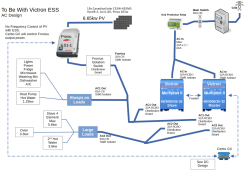
On a separate note I spoke with a designer here in Australia and was advised that setting up a Victron ESS system with a Multiplus was achievable here in Australia. They advised having the grid tie inverter at the end of the chain and then the Multiplus with a grid connection. The objective was not to export anything whatsoever, which is fine with me.
The grid tie inverter needs to be able to derate using frequency shifting so that it can dump load. Fronius, SMA and Fimer inverters are capable of doing it. There is also the 1:1 rule which means if you have a 5KW offgrid inverter then you can only have a 5KW max output grid connected inverter. I think this is so the Multiplus is able to shut down the grid inverter completely.
To kick all of this off I will put a 5KW grid tied inverter onto the house and put an offgrid system into my shed. Then once the shed system is running and reliable I will join the two systems together with a cable run. House is still being built so i am in limbo at the moment. My shed system is a baby 12V system running a DC water pump and a fridge only.
 ) This would mean you don't need to consider the size of the grid tied inverter as much too.
I assume you will have the Grid Tie Inverter on the AC Out of the Multiplus.They advised having the grid tie inverter at the end of the chain and then the Multiplus with a grid connection.
With Victron ESS & Fronius you do not need to use frequency shifting - see the Fronius Zero Feed-in option in ESS. It uses a direct communication connection between the Cerbo/Venus & Fronius for the Cerbo/Venus to control Fronius PV generation.The grid tie inverter needs to be able to derate using frequency shifting so that it can dump load. Fronius, SMA and Fimer inverters are capable of doing it.
The 1:1 rule only applies when the PV inverter is connected to Multiplus AC Out. This is so the max output of the PV inverter does not overwhelm to max output of the Multiplus.There is also the 1:1 rule which means if you have a 5KW offgrid inverter then you can only have a 5KW max output grid connected inverter.
What communication standard would the PV and Multiplus be using to control the PV inverter? if it can't control on the AC out by frequency shifting then that will be a challenge to me as the PV and Multiplus will be ~40m apart in my desired installation.I assume you will have the Grid Tie Inverter on the AC Out of the Multiplus.
With Victron ESS & Fronius you do not need to use frequency shifting - see the Fronius Zero Feed-in option in ESS. It uses a direct communication connection between the Cerbo/Venus & Fronius for the Cerbo/Venus to control Fronius PV generation.
The 1:1 rule only applies when the PV inverter is connected to Multiplus AC Out. This is so the max output of the PV inverter does not overwhelm to max output of the Multiplus.
AS @KangaRooted mentioned, there is no limit on the PV inverter size when it is connected to the Multiplus AC In. In this case you do not need to worry about frequency shifting/limiting PV inverter output.
I would like to have the capability to utilize the Fronius in a grid outage or isolated arrangement. If I end up going to Amber as my provider there are times I wont want to use the grid at all, and other times where I will utilize the grid connection.Unless the plan is to completely turn off the grid connection altogether, I don't understand why you couldn't/shouldn't/wouldn't have the inverter on the incoming line of the Multiplus. Afterall, the rule is that the Multiplus can't backfeed into the grid - not the grid tied inverter. The inverter charges your battery then continues to feed into the grid after the battery is full - (Disclaimer - I've NFI why you'd actually want to do this as the retail provider is stealing that feed in from you at 5c a Kw - but for the sake of the discussion... lets just pretend it might be a good idea
Was there any feedback from the designer on why one option might be okay and not the other? I'm keen to understand the thinking behind it.
Also, what did the designer say about "build your own battery"?
It uses Modbus via TCP over ethernet from CerboWhat communication standard would the PV and Multiplus be using to control the PV inverter? if it can't control on the AC out by frequency shifting then that will be a challenge to me as the PV and Multiplus will be ~40m apart in my desired installation.
So I will have to provide a direct connection between the Fronius and the Cerbo. Might have to pull some Cat6 when I do the cable runs to my shed.It uses Modbus via TCP over ethernet from Cerbo
See 4.3.13. AC-Coupled PV - Zero and Limited Feed-in with Fronius AC PV
Do yourself a favor and pull 2 or 3 runs. You never know when those extra ones may come in handy and you dont wanna have to dig up again if you drop it in a trench....So I will have to provide a direct connection between the Fronius and the Cerbo. Might have to pull some Cat6 when I do the cable runs to my shed.
Good Idea mate I will. Since its going to be CAT6 will pull a few pairs through. It will all be in conduit as well. I also have to pull through a few cables to do what I want to do with the ESS system.Do yourself a favor and pull 2 or 3 runs. You never know when those extra ones may come in handy and you dont wanna have to dig up again if you drop it in a trench....
Hi BipedalPrimate,@KangaRooted Installation is scheduled for 26 June.
Installed & even have a Certificate of Electrical Safety so it is all legal.how did the install on the 26th go, did you get across the line ok?
What Batteries did you use?
The intent was to have all the AC wiring done by an electrician and get a COES for that part because the AC is the most dangerous.What was installed exactly if the battery is still on its way? Can you share some more info about work completed?


Don't know - there was an initial application for the PV & Fronius which could have included a battery, but didn't. As I am not intending to feed the grid from the battery nor from the Victron's, this design is effectively a battery & inverters plugged into a power point with a Grid Protection Relay to intentionally island.Do you have to register your battery with the local wholesaler?
Not a word & seemed nonplussed by the intended design.Did the sparky have anything to say about it?
Changeover switch is 3 position so there is a period of no power when using it.can you just throw that changeover switch or is there a period of "no power" in your house when you flick the switch...
.Any update ? How did you go ?@KangaRooted Installation is scheduled for 26 June.